Wireless Communication
Purpose
The purpose of the Wireless Communication project (referred to in this report as the “WC Project”) is to learn the essential skill of wireless communication between Arduino boards, as well as reinforce time management and collaborative skills.
The first skill acquired through the completion of the WC Project is the essential skill of wireless communication between Arduino boards, which had not been explored to date in the course. These basic wireless communication skills have a wide range of applications for various more sophisticated projects.
The second skill reinforced through the completion of the WC Project is time management and collaboration. The WC Project requires a partner to use his Arduino and wireless module as the transmitter or receiver for communication. Working on a project of this type with a partner adds a new layer of complexity in terms of time management and collaboration skills needed in order to successfully complete the project.
| Parts List |
|---|
| 2 x 595 Shift Registers |
| LED Matrix Shield by E. Peterson |
| 2 x NRF24L01 Wireless Modules |
| LED Bargraph |
Reference
Procedure
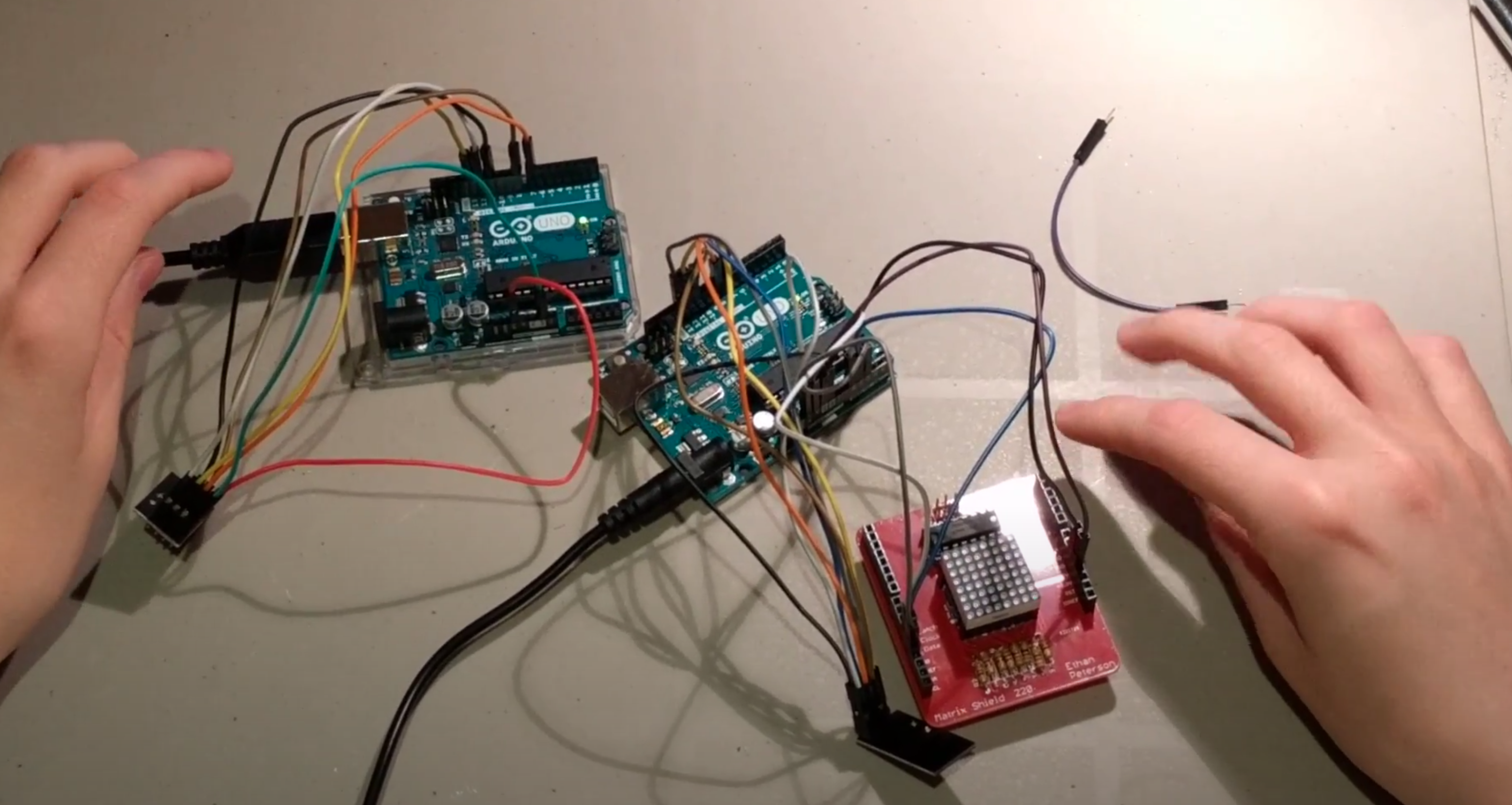
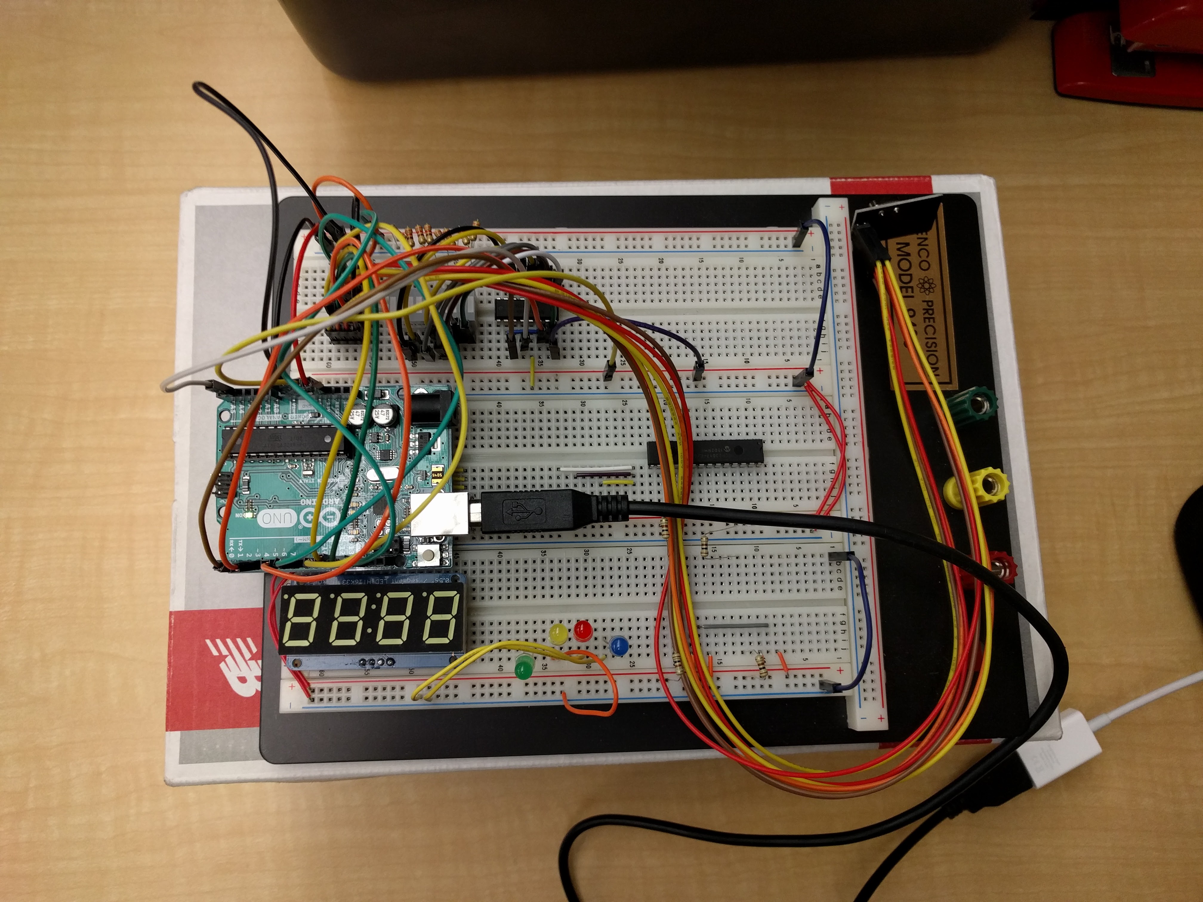
The WC Project is made up of two unique circuits. The first circuit is the transmitter, which consists of an Arduino connected to a wireless module. The second circuit acts as the receiver, consisting of an Arduino, wireless module and an LED Matrix Shield. However, the LED Matrix Shield designed by the undersigned was not initially the display device. The initial display device was an LED bar graph, which displayed the characters sent by the transmitter in their binary form. Students were encouraged to improve the base circuit that used a bar graph. The undersigned and his partner selected the LED Matrix Shield to display the letters sent over wireless, as opposed to their binary representation. With both circuits completed, Arduino code is used to set one circuit as the transmitter and the other as the receiver, transmitting the data by entering it into the serial monitor.
The creation of the WC Project is split into 3 steps; building the demo circuit, adding the bar graph display and serial input, and switching the bar graph to an LED Matrix Shield display.
The first and simplest step in the construction of the WC Project was to build the NRF24L01 demo circuit, which used two of the wireless modules to change the brightness of an LED connected to the receiving Arduino using a potentiometer. The code to complete this introduction was provided in class and served as a basis for the code in the actual project.
The second step in the creation of the WC Project was to take user input on the
transmitter circuit and send it to the receiver side for purposes of display on
an LED bar graph. First, a 595 shift register was connected to the receiver
Arduino along with the LED bar graph. Once the bar graph was hooked up to the
receiver Arduino, the code had to be modified for both the transmitter and
receiver. The changes to the transmitter code were quite simple: rather than
collecting the input from a potentiometer using the analogRead() function, the
Serial.read() function was used to collect whatever character the user last
entered into the serial monitor. Since the value being transmitted to the
receiver Arduino is an ASCII character, that ASCII character has its own number
value, therefore making the display of the binary value of the character on the
bar graph very straightforward. The receiver code had to be modified to display
the binary value of the ASCII character on the bar graph using a single call to
the shiftOut() function built into the Arduino IDE used for transmitting data to
shift registers. Since each ASCII character has a number value, the received
character itself was simply passed into the shiftOut() function and shown on the
bar graph.
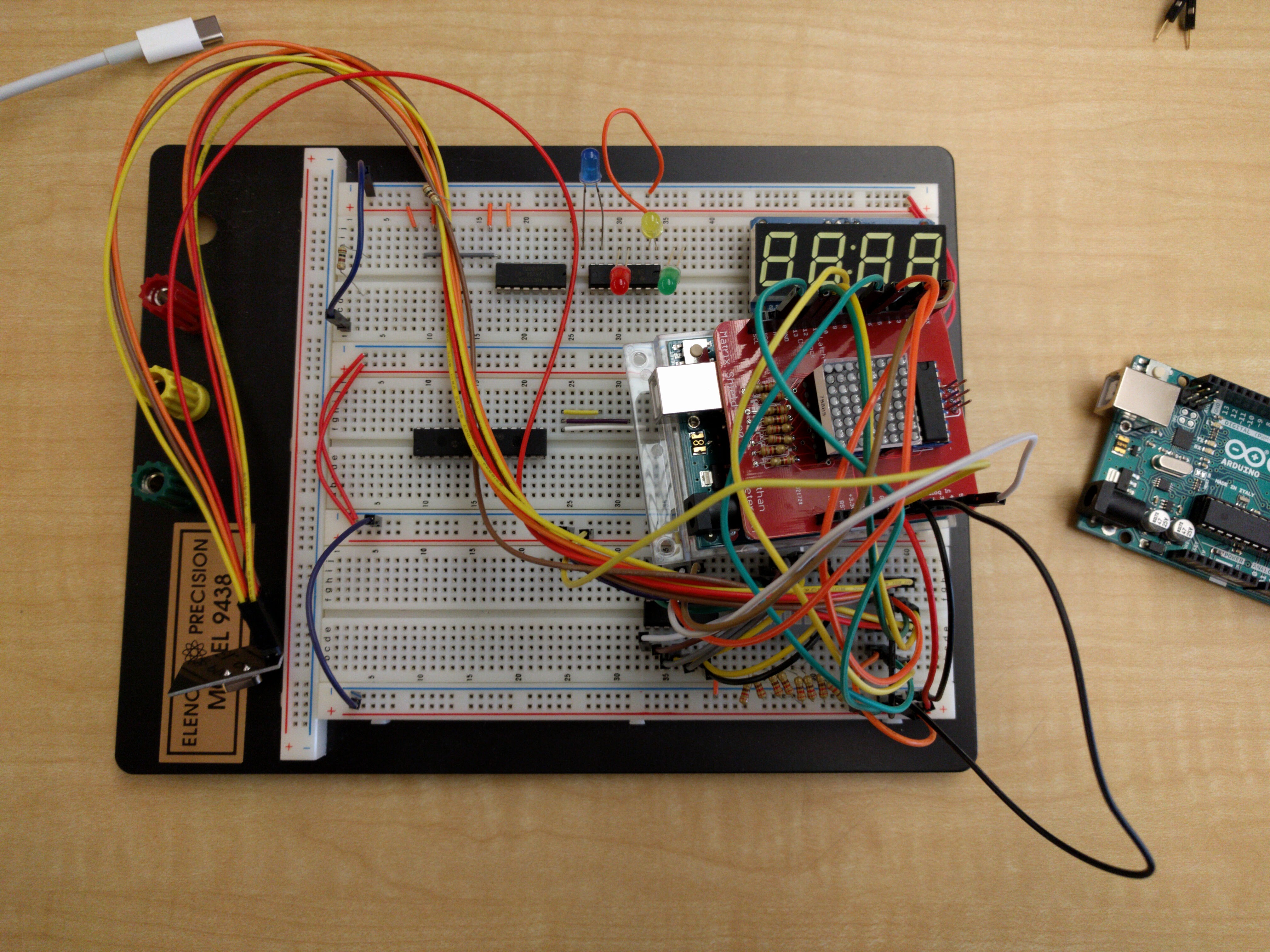
The third and most difficult step in building the WC Project was using an LED matrix as the output device. Displaying the received character on the LED Matrix Shield was very difficult at first. The shield was placed atop the Arduino Uno, which acted as the receiver. The wireless module was then hooked up to the female headers on the shield. After the addition of the shield, an issue arose where no data at all could be transmitted between the Arduinos or displayed on the LED matrix. Following a long period of arduous troubleshooting, it was discovered that the pins used to drive the shift registers and LED matrix on the shield are the same pins that were hard wired for the SPI protocol in the radio library. This issue was circumvented by disconnecting the shield from the Arduino and connecting different pins on the Arduino to the shift register pins on the shield. Once the shield was properly set up, the ASCII value for each
letter in the alphabet had to be associated with a corresponding bitmap to be displayed on the LED Matrix. For in-depth information on bitmaps and displaying images on an LED matrix, refer to the TBMA project report in this document. The undersigned’s partner, Jasper Schaffer, provided the bitmaps for every letter in the alphabet, which were associated to their corresponding ASCII value using a large switch case. A big switch case to handle the issue of matching ASCII values with the correct bitmap was not the initial plan. Initially, the plan was to save the bitmaps in EEPROM, however, each address in EEPROM only has space for one byte while a bitmap for the LED matrix consists of 8 bytes. The idea was to store each bitmap in the address that matched its ASCII value, which would make collecting the correct bitmap for the received character very simple. Since each bitmap would take up 8 slots in EEPROM, it was impossible to save a bitmap at the correct address as that address would already be populated with the data from another bitmap. For instance, the ASCII value of the character “A” is 65. If the bitmap for “A” was saved at EEPROM address 65, address 66 (which is the ASCII value for “B”) would already be overwritten with data from “A”. This convenient model for collecting character bitmaps would only work with bitmaps that occupy one byte of space. Once the switch case was completed, the matrix would display the correct bitmap for the ASCII character received.
Media
Code
#include <nRF24L01.h>
#include <printf.h>
#include <RF24.h>
#include <RF24_config.h>

#define RECEIVER 1
#define TRANSMITTER 0

#define clk A1
#define latch A0
#define data A2
#define shiftRegNum 2
#define shiftRegPinNum shiftRegNum * 8

byte inputChar;
byte readChar;
bool radioNumber = RECEIVER;

uint8_t received = 0;
uint8_t currentBitMap[8];
RF24 radio(7, 8);

byte addresses[][6] = {"1Node", "2Node"};
bool registers[shiftRegPinNum];

const uint8_t alphabet[][8] = { // bit maps for every letter in the alphabet from A - Z
{
B00011000,
B00100100,
B00100100,
B01000010,
B01111110,
B01000010,
B01000010,
B01000010
},{
B11111000,
B10000100,
B10000100,
B11111100,
B10000100,
B10000010,
B10000010,
B11111100
},{
B00111100,
B01000000,
B10000000,
B10000000,
B10000000,
B10000000,
B01000000,
B00111100
},{
B11111100,
B10000010,
B10000001,
B10000001,
B10000001,
B10000001,
B10000010,
B11111100
},{
B11111110,
B10000000,
B10000000,
B11111100,
B10000000,
B10000000,
B10000000,
B11111110
},{
B11111110,
B10000000,
B10000000,
B11111100,
B10000000,
B10000000,
B10000000,
B10000000
},{
B01111111,
B10000000,
B10000000,
B10000000,
B10000000,
B10000110,
B10000001,
B01111110
},{
B10000001,
B10000001,
B10000001,
B11111111,
B10000001,
B10000001,
B10000001,
B10000001
},{
B01111110,
B00011000,
B00011000,
B00011000,
B00011000,
B00011000,
B00011000,
B01111110
},{
B11111111,
B00001000,
B00001000,
B00001000,
B00001000,
B01001000,
B01001000,
B00111000
},{
B10000000,
B10001100,
B10010000,
B11100000,
B10100000,
B10010000,
B10001000,
B10000100
},{
B10000000,
B10000000,
B10000000,
B10000000,
B10000000,
B10000000,
B10000010,
B11111110
},{
B10000001,
B11000011,
B10100101,
B10100101,
B10100101,
B10011001,
B10011001,
B10011001
},{
B10000001,
B11000001,
B10100001,
B10010001,
B10001001,
B10000101,
B10000011,
B10000001
},{
B00111100,
B01000010,
B10000001,
B10000001,
B10000001,
B10000001,
B01000010,
B00111100
},{
B11111000,
B10000100,
B10000100,
B10000100,
B11111000,
B10000000,
B10000000,
B10000000
},{
B00111100,
B01000010,
B01000010,
B01000010,
B01000010,
B01000110,
B01000010,
B00111101
},{
B01111000,
B01000100,
B01000100,
B01111000,
B01100000,
B01010000,
B01001000,
B01000100
},{
B00111110,
B01000000,
B01000000,
B01111110,
B00000010,
B00000010,
B00000010,
B01111100
},{
B11111111,
B00001000,
B00001000,
B00001000,
B00001000,
B00001000,
B00001000,
B00001000
},{
B10000001,
B10000001,
B10000001,
B10000001,
B10000001,
B10000001,
B10000001,
B01111110
},{
B01000001,
B01000001,
B01000001,
B01000001,
B00100010,
B00100010,
B00010100,
B00001000
},{
B01000001,
B01000001,
B01000001,
B01000001,
B01001001,
B01010101,
B01010101,
B00100010
},{
B11000011,
B00100100,
B00100100,
B00011000,
B00011000,
B01100110,
B10000001,
B10000001
},{
B00100010,
B00100010,
B00010100,
B00001000,
B00001000,
B00001000,
B00001000,
B00001000
},{
B11111111,
B10000010,
B00000100,
B00001000,
B00010000,
B00100000,
B01000001,
B11111111
}};

void setup() {
  // put your setup code here, to run once:
  radio.begin(); // initialize radio and serial
  Serial.begin(9600);
  // Clear shift reg values on the shield
  clearRegs();
  writeRegs();
  // set shift register pins to output
  pinMode(clk, OUTPUT);
  pinMode(latch, OUTPUT);
  pinMode(data, OUTPUT);
  radio.setPALevel(RF24_PA_LOW);
  radio.setChannel(105);
  if (radioNumber == RECEIVER) {
    radio.openWritingPipe(addresses[1]);
    radio.openReadingPipe(1, addresses[0]);
  } else {
    radio.openWritingPipe(addresses[0]);
    radio.openReadingPipe(1, addresses[1]);
  }
  radio.startListening();
}

void loop() {
  if (radioNumber == TRANSMITTER) {
    radio.stopListening();
    readChar = readSerial();
    // attempt to write data and if the transmission fails print something
    if (!radio.write(&readChar, sizeof(uint8_t))) {
      Serial.println("Failed");
    }
    radio.startListening();
  }
  if (radioNumber == RECEIVER) {
    inputChar = readWireless(); // read in received character if any
    getChar(inputChar);         // get appropiate bitmap
    Serial.println(inputChar);  // print received char
    // display bitmap placed in currentBitMap variable by getChar function
    displayChar(currentBitMap);
  }
}

byte readSerial() { // reads in the character typed into the serial monitor
  while (Serial.available()) {
    byte charRead = Serial.read(); // reads ASCII value of character typed
    return charRead;
  }
}

byte readWireless() { // reads in data received by the wireless module
  byte received;
  while (radio.available()) {
    radio.read(&received, sizeof(uint8_t));
  }
  return received;
}

void clearRegs() { // clears the registers array but does not write the changes
  for (int i = shiftRegPinNum - 1; i >= 0; i--) {
    registers[i] = LOW;
  }
}

// writes data in the registers array to the output pins of the shift registers
void writeRegs() {
  digitalWrite(latch, LOW);
  for (int i = shiftRegPinNum - 1; i >= 0; i--) {
    digitalWrite(clk, LOW);
    uint8_t val = registers[i];
    digitalWrite(data, val);
    digitalWrite(clk, HIGH);
  }
  digitalWrite(latch, HIGH);
}

// function changes the value of an individual pin on the 595 by changing the
// value in the registers array where the change can be displayed later
void setRegPin(uint8_t i, uint8_t val) { registers[i] = val; }

// this is taking place so fast that it looks as though all rows are being
// illuminated at the same time
void displayChar(uint8_t charMap[8]) {
  // ensure column data is shown on the correct row by illuminating the current
  // one and making the previous one low
  for (uint8_t row = 0; row < 8; row++) {
    setRegPin((row - 1), 0);
    setRegPin(row, 1);
    for (uint8_t col = 0; col < 8; col++) {
      if (charMap[row] & (1 << (7 - col))) {
        // invert the bit because col pins must be low to be shown due to the
        // way the matrix is configured
        setRegPin(8 + col, 0);
      } else {
        setRegPin(8 + col, 1);
      }
    }
    if (row == 0) {
      setRegPin(7, LOW); // prevent same byte from being shown on two columns
    }
    writeRegs();
  }
}

// copies matrix bitmaps from variable to currentBitMap var
void copy(uint8_t from[8]) {
  for (int i = 0; i < 8; i++) {
    currentBitMap[i] = from[i];
  }
}

// sets variable currentBitMap to the correct bitmap depending on the character
// received
void getChar(uint8_t input) {
  switch (input) {
  case 'A':
    copy(alphabet[0]);
    break;
  case 'B':
    copy(alphabet[1]);
    break;
  case 'C':
    copy(alphabet[2]);
    break;
  case 'D':
    copy(alphabet[3]);
    break;
  case 'E':
    copy(alphabet[4]);
    break;
  case 'F':
    copy(alphabet[5]);
    break;
  case 'G':
    copy(alphabet[6]);
    break;
  case 'H':
    copy(alphabet[7]);
    break;
  case 'I':
    copy(alphabet[8]);
    break;
  case 'J':
    copy(alphabet[9]);
    break;
  case 'K':
    copy(alphabet[10]);
    break;
  case 'L':
    copy(alphabet[11]);
    break;
  case 'M':
    copy(alphabet[12]);
    break;
  case 'N':
    copy(alphabet[13]);
    break;
  case 'O':
    copy(alphabet[14]);
    break;
  case 'P':
    copy(alphabet[15]);
    break;
  case 'Q':
    copy(alphabet[16]);
    break;
  case 'R':
    copy(alphabet[17]);
    break;
  case 'S':
    copy(alphabet[18]);
    break;
  case 'T':
    copy(alphabet[19]);
    break;
  case 'U':
    copy(alphabet[20]);
    break;
  case 'V':
    copy(alphabet[21]);
    break;
  case 'W':
    copy(alphabet[22]);
    break;
  case 'X':
    copy(alphabet[23]);
    break;
  case 'Y':
    copy(alphabet[24]);
    break;
  case 'Z':
    copy(alphabet[25]);
    break;
  }
}
Conclusion
Overall, the WC Project allowed for the essential skills of wireless communication, as well as time management and collaboration to be developed. This project resulted in a final product that can be expanded upon into various interesting projects in the future.