Fingerprint Enabled Doorlock
Purpose
The purpose of the Fingerprint Enabled Door Lock (referred to in this report as the FEDL) was to create a useful and fun device while bolstering knowledge of the I2C bus from the last challenge, improving programming ability and most importantly, using EAGLE to design custom PCBs.
The first skill that was improved in this project was the use of the I2C bus. Knowledge in this case was improved following an in-class unit on the interface and Challenge 3.
The second skill improved throughout the duration of the FEDL project was programming. The Arduino sketch for this project was the largest written to date due to the various components that were used.
The third and most important skill obtained during the FEDL project was a working knowledge of the Cadsoft EAGLE software, which is used for the purpose of designing custom circuit schematics and boards. These designs can subsequently be submitted to a PCB fabricator for production and shipment of custom PCBs. The skill of PCB design is essential for larger circuits and projects where a standard proto-board cannot be used.
| Parts List |
|---|
| Custom PCB |
| Adafruit Optical Fingerprint Reader |
| LED Bar Graph |
| 11 x 220Ω Resistors |
| 2 x 10k Ω Resistor |
| Adafruit Chronodot Real Time Clock Module (RTC) |
| Adafruit I2C 7-Segment Backpack |
| Servo Motor |
| Acrylic Chassis & Lock |
| Push Button |
| Arduino Uno |
| MCP23017 I/O Expander |
| RGB LED (Common Cathode) |
Reference
PCB Manufacturer Used: Advanced Circuits
Procedure
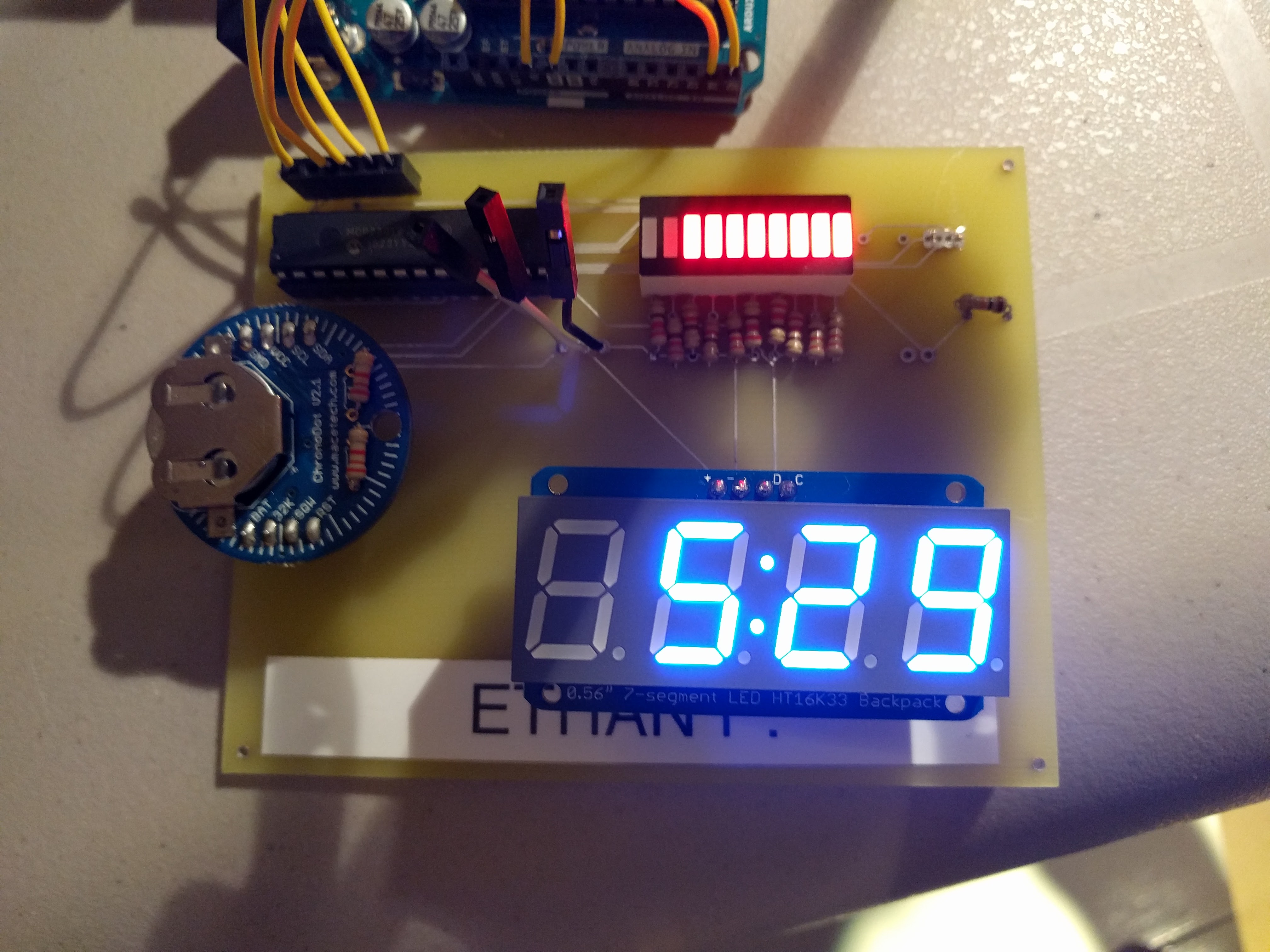
The FEDL project consists mainly of a MCP23017 I2C I/O expander, an LED bar graph, a Chronodot, an I2C 7-Segment Backpack, a servo motor and an Adafruit Fingerprint Sensor. The Circuit is housed on a custom PCB, connecting the I/O expander to the Arduino along with the Chronodot and 7-Segment Display via I2C. The custom board connects the I/O expander to the LED bar graph and button. The custom PCB also has input pins from the Arduino to communicate with the fingerprint sensor and servo outside of the I2C bus. With the custom board tying all of the components together, Arduino code can be used to create an effective door lock system.
The construction of the FEDL is broken down into 3 steps: Prototype circuit, board design and fabrication and the code.
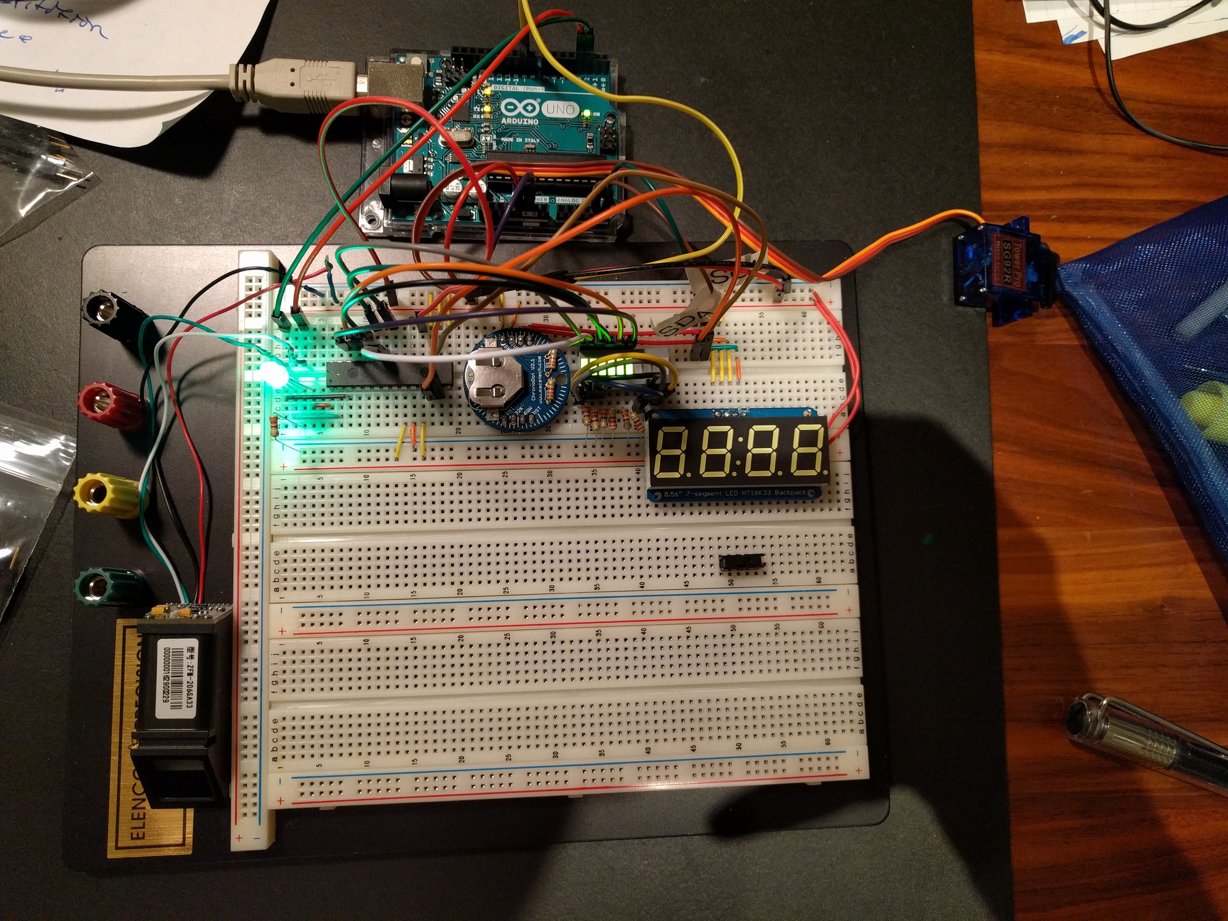
Prototyping the circuit is the first and easiest step in the making of the FEDL. Since the circuit contains many I2C components, the wiring for most of the circuit involves connecting the SDA and SCL pins to the various components. The connection of the fingerprint scanner and servo motor requires only 3 pins each, making the wiring of the FEDL circuit extremely straightforward.
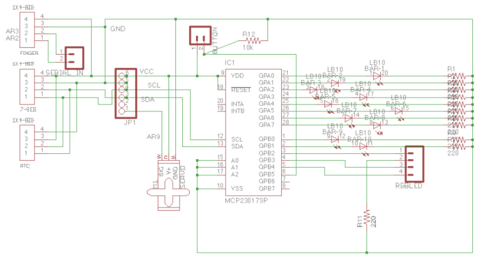
The second and most difficult step of building the FEDL was the board design and fabrication. The process of designing a custom PCB involved learning how to use the Cadsoft EAGLE software. EAGLE is the most common software used for board design. The first step was to create a working schematic within EAGLE. This required finding all of the parts needed for the circuit within the EAGLE part picker. Once the schematic was completed and checked as thoroughly as possible for errors, the EAGLE software was switched to board view. The board view function was used to place the parts on the board in the desired fashion. Once the PCB was laid out properly, the next step was to run the autorouter. The autorouter automatically connects the components as specified in the schematic by placing physical traces that will be printed on the board when it is ordered. Following the completion of the routing, the board was ordered from a PCB fabrication company called Advanced Circuits. The first iteration of the FEDL PCB was delivered a few days later. An issue was encountered with the first PCB in that the pads where the RGB LED would be soldered were connected and would therefore cause a short circuit. The DRC (Design Rule Check) function within EAGLE warned of this, however, it was initially thought that the issue could be simply fixed by cutting the traces on the board manually. Despite the RGB LED issue, the rest of the board had to be tested. The first custom PCB was soldered excluding the RGB LED and it functioned properly. Once it was determined that the first design functioned properly, EAGLE was used to change the design of the board to fix the error with the RGB LED by using a simple pin header component instead of a component specifically designed for a RGB LED. Additionally, a pin header was added to the board for the Arduino software serial pins required to operate the fingerprint sensor, which was omitted from the previous design as it was thought that the fingerprint scanner could be directly connected to the Arduino. The second iteration of the board was ordered and delivered approximately one week prior to the ISP presentation date allowing ample time for soldering and testing. Once the board was soldered and tested, it was mounted along with the Arduino on a slab of acrylic, which acted as a chassis for the components.

The third and final step of building the FEDL project was the programming. With
the custom PCB already soldered and tested, a functioning circuit had been
produced and the programming process could commence. The first step of the
programming process was using the Wire library to read time data from the
Chronodot RTC. Developing this functionality required the use of the Chronodot’s
datasheet, which indicated which addresses within the chip’s memory had the
required information (such as hour and minute). Once data was successfully
retrieved from the Chronodot, two new functions called hour() and minute() were
created that returned the current hour and minute as an integer. The time
obtained from these functions was displayed on the 7-Segment display using
Adafruit’s library. The second step of the programming process was to operate
the I/O pins on the MCP23017 in the same manner as on the Arduino. Three
functions were developed for this purpose: mcWrite(), mcRead() and mcPinMode(),
which recreated the digitalWrite(), digitalRead() and pinMode()
functions on the Arduino. Completing these new functions required the Wire
library and extensive use of bitwise operators as the functions had to have the
ability to change bits in the MCP23017’s registers. The third step of the
programming process was to read data from the fingerprint scanner and check if
the correct finger is placed on the sensor. Adafruit’s fingerprint scanner
library was used to achieve this.
Demo
Code
#include "Arduino.h"
#include <Servo.h> // For easy control of a servo for locking and unlocking the door
#include <SoftwareSerial.h> // For Serial communication with the fingerprint sensor
#include <Wire.h>           // For I2C communication between various components

// 7 Segment Backpack libraries:
#include "Adafruit_LEDBackpack.h"
#include <Adafruit_GFX.h>
// Fingerprint Scanner Library:
#include <Adafruit_Fingerprint.h>

#ifndef SYMBOL
#define expanderAddress 0x20 // i2c address of MCP23017
#define portADir 0x00 // Direction Register address for PORT A (pins 0-7 will be PORTA)
#define portBDir 0x01 // Direction Register address for PORT B (pins 8 - 15 will be PORT B)

// GPIO PORT A and B addressing
#define portA 0x12
#define portB 0x13
// 7-Segment Backpack Address:
#define displayAddress 0x70

// RTC address
#define timeAddress                                                            \
  0x68 // I2C address to access time registers on the Chronodot

// BCD to decimal converter for values read from the RTC
// preprocessor definition of a function
#define bcdToDec(bcdVal)                                                       \
  (((bcdVal & 0b11110000) >> 4) * 10 + (bcdVal & 0b00001111))

// define button pin
#define button 13

// define function to check if nth bit is set or cleared in byte
#define bitCheck(inputVar, position) ((inputVar) & (1 << position))
#define fingerId 0   // id # of my fingerprint stored in the senor
#define servoPin 9   // PWM pin on arduino used to control the Servo Motor
#define lockedPos 85 // servo position for locked door
#define openPos 180  // servo positon for unlocked door
#endif

          Adafruit_7segment clockDisplay = Adafruit_7segment();

SoftwareSerial mySerial(2, 3);
Adafruit_Fingerprint finger = Adafruit_Fingerprint(&mySerial);

Servo servo;

// make variables to hold the values in each of the MCP23017's registers
// pin direction registers
uint8_t portADirValue = 255;
uint8_t portBDirValue = 255;

// pin value registers
uint8_t portAValue = 0;
uint8_t portBValue = 0;

bool buttonState;
bool locked;

// MCP23017 functions
void mcPinMode(uint8_t pin, bool state) {
  Wire.beginTransmission(expanderAddress);
  if (pin < 8) {
    Wire.write(portADir); // map pins 0-7 to register A
    portADirValue ^= (~(-state) ^ portADirValue) & (1 << pin); // change bit at pin location to whatever the state boolean is
        // state boolean is inverted because OUTPUT and INPUT values are
        // inverted on MCP23017 (OUTPUT = 0, INPUT = 1)
        Wire.write(portADirValue);
  } else { // if is greater or equal to 8
    Wire.write(portBDir);
    portBDirValue ^= (~(-state) ^ portBDirValue) & (1 << (pin - 8));
    Wire.write(portBDirValue);
  }
  Wire.endTransmission();
}

void mcWrite(uint8_t pin, bool state) {
  Wire.beginTransmission(expanderAddress);
  if (pin < 8) {
    Wire.write(portA);
    portAValue ^= (-state ^ portAValue) & (1 << pin);
    Wire.write(portAValue);
  } else {
    Wire.write(portB);
    portBValue ^= (-state ^ portBValue) & (1 << (pin - 8));
    Wire.write(portBValue);
  }
  Wire.endTransmission();
}

bool mcRead(uint8_t pin) { // function serving the same purpose as digitalRead()
  // that works for the MCP23017
  Wire.beginTransmission(expanderAddress);
  uint8_t bitToAccess = pin;
  uint8_t dataRead; // stores input byte obtained from MCP23017
  if (pin < 8) {
    Wire.write(portA);
  } else {
    Wire.write(portB);
    bitToAccess = pin - 8;
  }
  Wire.endTransmission();
  // request the data
  Wire.requestFrom(expanderAddress, 1);
  dataRead = Wire.read();
  return bitCheck(dataRead,
                  bitToAccess); // returns true if the bit is set and
  // false if not
}
// RTC time collection functions
uint8_t hour() { // returns hour (0 - 24)
  Wire.beginTransmission(timeAddress);
  Wire.write(0x02); // start reading data from hours register on the Chronodot
  Wire.endTransmission();
  // request one byte from the RTC since we start
  // reading data from the hours register we will get hours
  Wire.requestFrom(timeAddress, 1);
  uint8_t hours =
      Wire.read(); // mask required due to control bits on hour register &0x3f
  // different BCD to Decimal conversion requied
  // due to control bits on hour register
  hours = (((hours & 0b00100000) >> 5) * 20 + ((hours & 0b00010000) >> 4) * 10 +
           (hours & 0b00001111));
  return hours;
}

uint8_t minute() { // returns minute (0 - 59)
  Wire.beginTransmission(timeAddress);
  Wire.write(0x01); // start at minutes register on Chronodot
  Wire.endTransmission();
  // request minute data
  Wire.requestFrom(timeAddress,
                   1); // request one byte which is the minute value
  uint8_t minutes = Wire.read();
  // no mask required on minute register simply convert to decimal
  return bcdToDec(minutes);
}

// 7-Segment display functions (and other code to do with visual output)
void showTime() {
  // setup variable to print to 7-Segment displays
  uint8_t h = hour();
  uint8_t m = minute();
  int theTime = h * 100 + m;
  // do 24 to 12 hour time conversion
  if (h > 12) {
    theTime -= 1200;
  } else if (h == 0) { // handle midnight where h = 0
    theTime += 1200;
  }
  clockDisplay.print(theTime);

  // show colon on the display between hour and min
  clockDisplay.drawColon(true);
  clockDisplay.writeDisplay(); // show changes on the display
}

// shows progress of door being unlocked on bargraph
void showBars(uint8_t barNum) {
  // clear Bargraph first
  for (int j = 9; j >= 1; j--) {
    mcWrite(j, LOW);
  }
  // display specified # of bars on led bargraph
  for (int i = 0; i < barNum; i++) {
    mcWrite(i, HIGH);
  }
}

typedef struct {
  uint8_t red;
  uint8_t green;
  uint8_t blue;
} RGBLed;
RGBLed rgb = {10, 11, 12};

// Fingerprint sensor code
uint8_t getID() {
  uint8_t f = finger.getImage();
  if (f != FINGERPRINT_OK) {
    return -1;
  }
  f = finger.image2Tz();
  if (f != FINGERPRINT_OK) {
    return -1;
  }
  f = finger.fingerFastSearch();
  if (f != FINGERPRINT_OK) {
    return -1;
  }
  return finger.fingerID;
}

// changes door from locked to unlocked depending on bool passed to the
// function
void lockState(bool state) {
  servo.attach(9);
  if (state) {
    for (int i = openPos; i >= lockedPos; i--) {
      servo.write(i);
      uint8_t bars = map(servo.read(), lockedPos, openPos, 0, 11);
      showBars(bars);
      delay(25);
    }
  } else {
    for (int j = lockedPos; j < openPos; j++) {
      servo.write(j);
      uint8_t bars = map(servo.read(), lockedPos, openPos, 0, 11);
      showBars(bars);
      delay(25);
    }
  }
  servo.detach(); // prevent noise
}

void scan() { // runs in a loop scanning for a correct fingerprint on the sensor
  bool fingerAvailable = finger.verifyPassword();
  if (getID() == fingerId && fingerAvailable) {
    mcWrite(rgb.green, HIGH);
    mcWrite(rgb.red, LOW);
    Serial.println("FOUND ID: ");
    Serial.print(fingerId);
    locked = !locked;
    lockState(locked);
  } else {
    mcWrite(rgb.green, LOW);
    mcWrite(rgb.red, HIGH);
  }
}

void buttonScan() {
  buttonState = mcRead(button);
  delay(100);
  if (buttonState != mcRead(button)) {
    locked = !locked;
    lockState(locked);
  }
}

void initIO() {
  Wire.begin();
  pinMode(A4, OUTPUT);
  pinMode(A5, OUTPUT);
  Serial.begin(9600);
  // Set all pins on MCP23017 to input by default
  Wire.beginTransmission(expanderAddress);
  Wire.write(portADir);
  Wire.write(255);
  Wire.endTransmission();
  // PORT B
  Wire.beginTransmission(expanderAddress);
  Wire.write(portBDir);
  Wire.write(255);
  Wire.endTransmission();
  for (uint8_t i = 0; i < 10; i++) { // Set pins 0-9 to OUTPUT for led bargraph
    mcPinMode(i, OUTPUT);
    mcWrite(i, LOW);
  }
  // initialize the 7-Segment Display
  clockDisplay.begin(displayAddress);
  finger.begin(57600);
  // initialize Servo
  servo.attach(servoPin);
  // Set RGB LED pins to OUTPUT
  mcPinMode(rgb.red, OUTPUT);
  mcPinMode(rgb.green, OUTPUT);
  mcPinMode(rgb.blue, OUTPUT);
}

void setup() { initIO(); }

void loop() {
  scan();
  showTime();
  buttonScan();
}
Conclusion
Overall, the FEDL was a challenging project that allowed for growth in the areas of programming and circuit board design. The project culminated in a product that is useful on an everyday basis.