Bi-Color LED Matrix
Purpose
The purpose of the BiColor LED Matrix Project (referred to in this report as the “BCLM”) is to improve the abilities of grade 11 ACES students in utilizing registers and bitwise operators through mid-level C programming. The BCLM project also serves as an opportunity for grade 11 students to be introduced to lower level programming, which will be further expanded upon in grade 12.
The first skill obtained in the BCLM project is the use of various bitwise operators such as left shift, right shift, bitwise AND, bitwise OR and bitwise NOT. The use of these operators gives lower level access to the registers of the microcontroller and therefore makes for more efficient programs.
The second skill acquired in the BCLM project is register manipulation on a microcontroller, which was used to form images on the LED Matrix and will be a very important skill for students who pursue the grade 12 ACES course.
Lastly, the essential skill of soldering is improved upon in the BCLM project as the BiColor LED Matrix used for the project is hand soldered.
| Parts List |
|---|
| ATtiny84 Microcontroller |
| LED Matrix Soldering Jig |
| 16 x BiColor LEDs |
| Sparkfun AVR Pocket Programmer |
| ISP Header PCB |
| 3D Printed LED Matrix Cover |
Reference
Procedure
The BCLM project consists of a 4x4 BiColor LED Matrix and an ATtiny84
microcontroller. 8 digital pins are required to control the LED Matrix. The
ATtiny84 has two ports: PORTA and PORTB. The LED Matrix is hooked up to PORTA in
the circuit as PORTA holds a full 8 pins on ATtiny84 while PORTB does not. By
hooking up the LED Matrix to PORTA, the whole matrix can be controlled from one
register. The fact that the LED Matrix can be controlled from one register is
very useful when programming since students have to use register manipulation
instead of Arduino functions like digitalWrite(). The construction of the BCLM
project is broken up into the following 3 steps; soldering and circuit
construction, animation planning and programming of the aforementioned
animations.
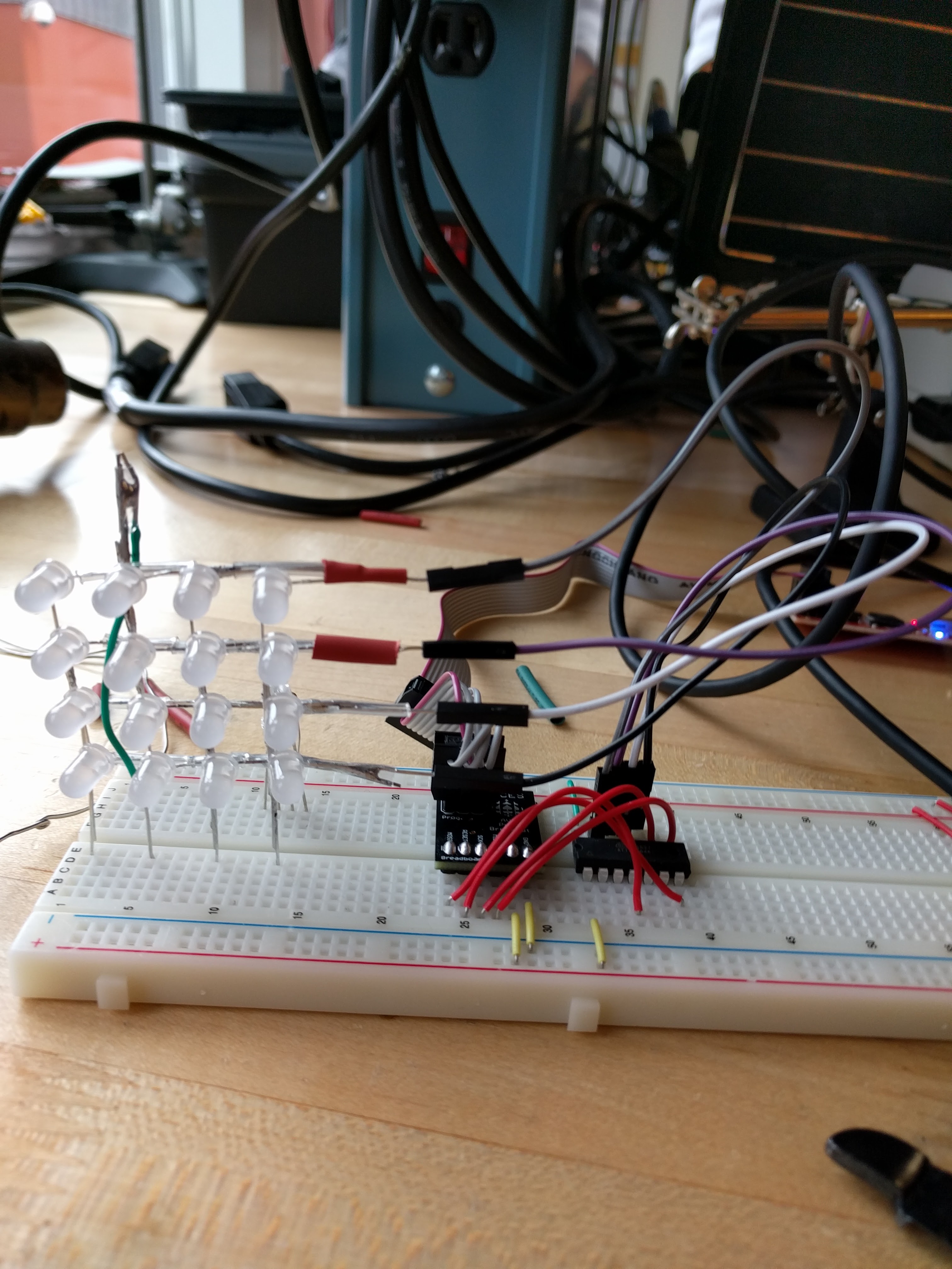
The first step of the BCLM project’s construction was to solder the LED Matrix. The soldering process proved to be difficult as the legs of each LED had to be properly insulated with heat shrink to prevent contact between different LED leads that would cause a short circuit. In instances where heat shrink was omitted by the undersigned in error, the risk of a short circuit from leads of two different LEDs accidentally connecting was somewhat alleviated by using pliers to create the largest distance between leads as possible.
Another issue during the soldering process was keeping the LEDs aligned in an even grid. The alignment issue was solved by using a 3D printed matrix jig (pictured on the right) for hand soldering LED matrices. The jig kept the LEDs evenly spaced and made it easier to solder. Once the soldering was complete, the matrix was placed in the breadboard. The PORTA pins on the ATtiny84 were hooked up sequentially along the matrix from PA0 to PA7. Specifically, the upper nibble of PORTA was connected to the row pins of the LED Matrix while the lower nibble was connected to the columns.
The second step of constructing the BCLM project was to plan out what animations would be shown on the LED Matrix. Creating an animated pattern involved planning out the value for the PORTA and DDRA registers for each frame of the animation. Both the PORTA and DDRA registers consist of 8 bits, the behaviour of the PORTA pins on the ATtiny84 is controlled by the values inside of both these two registers. The DDRA register is the data direction register for PORTA. For instance, setting the bit to a 1 at position 0 in the DDRA register would set the corresponding PA0 pin to be an output. On the other hand, setting it to a zero would make it an input. The PORTA register controls the state of the pins assigned to PORTA on the ATtiny84. For example, setting the bit at position 7 to a 1 on the PORTA register would cause pin PA7 to go high while a 0 would cause it to go low. However, the ability to set pins high and low on PORTA can only be utilized when those pins are set to output in the DDRA register, which is why both registers must be used in tandem to create matrix animations. The process of creating images on the LED Matrix was simplified by a planning sheet provided to all grade 11 students, which helped the undersigned visualize the image and see what values would be required in each register to display the desired image. The planning sheet also reintroduced the use of hexadecimal numbering, which is a far more concise way than expressing the value on each register as binary.
The final and most difficult step in the construction of the BCLM project was
writing the code. The process of writing the code began with creating more
simple animations that utilized bitwise operators, iteration and delays as
opposed to playing through a “hard coded” set of bitmaps. Each of these simple
animations were placed in their own functions that were called in void loop().
Once the simple animations were complete, more complex functions requiring
persistence of vision (POV) were pursued in void loop(). The use of POV allowed
for irregular shapes that could not be shown in a single image but in multiple
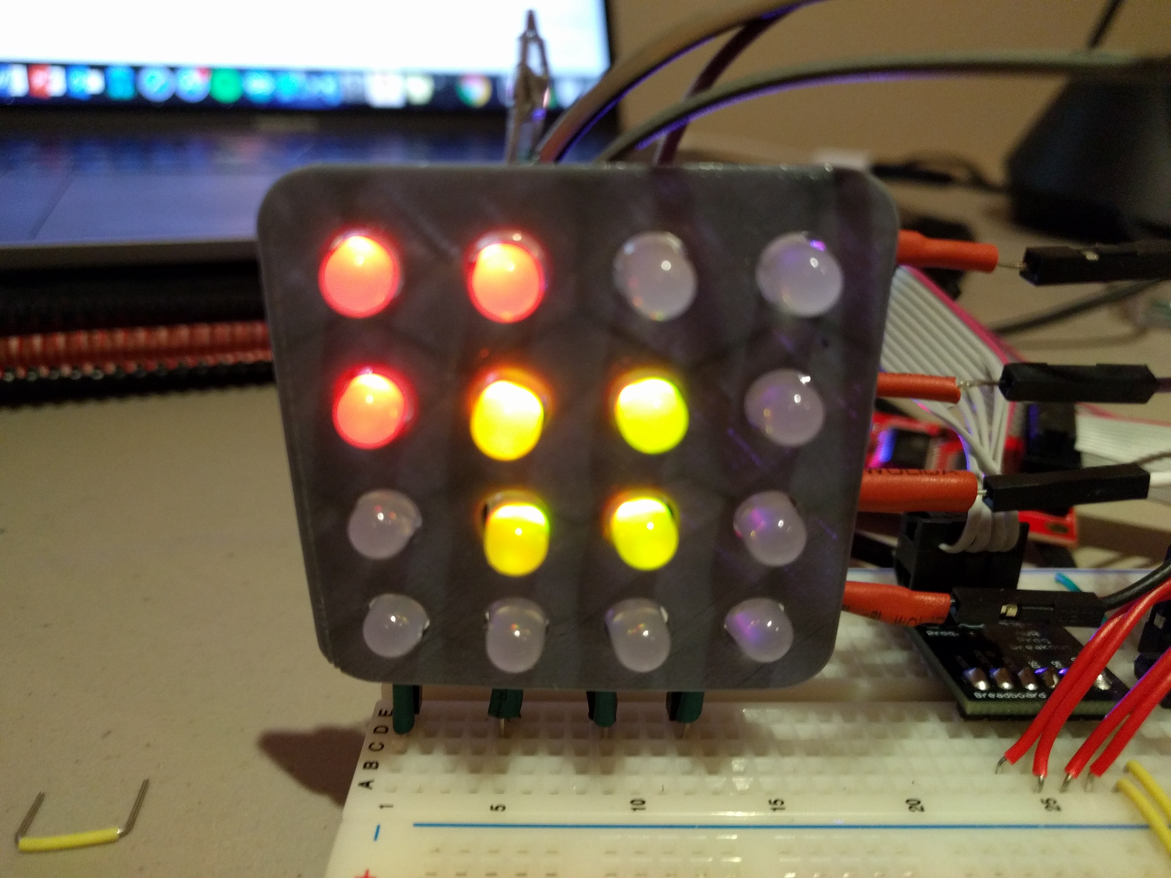
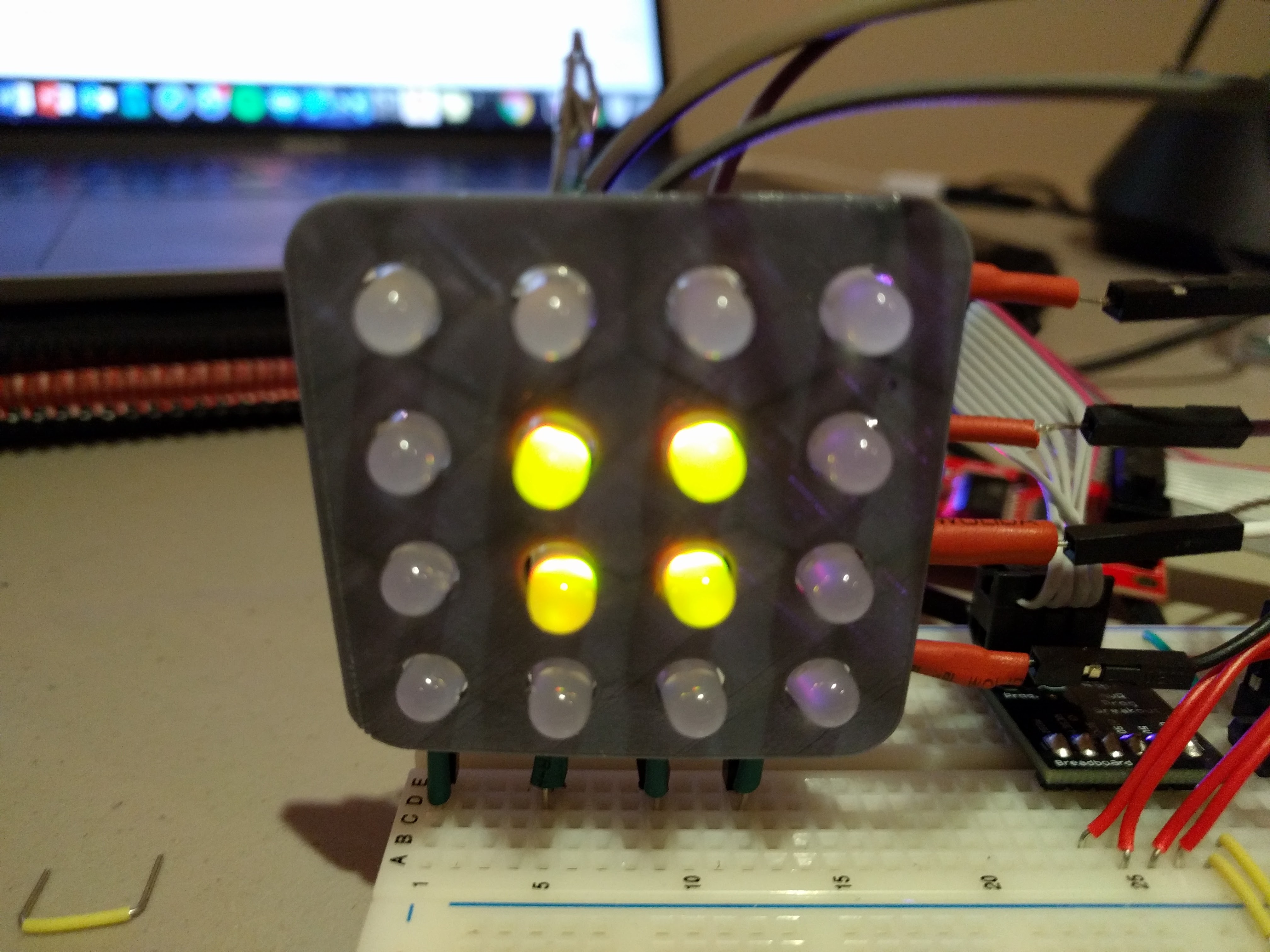
images displayed rapidly enough to look as though they are one. Please refer to
the report on the TBMA project for additional information about how POV works.
Pictured below is an image shown on the LED Matrix that relies on POV.
The first step in setting up POV was to design a structure to more closely
relate the unique data that is stored in each register for each frame in the POV
image. The structure created was called regPair. The structure contained a
variable called port and another variable called ddr which stores the data for
both of those registers in one structure.
The second step to set up POV was to initialize a timer overflow interrupt that
would change which image was displayed at regular time intervals. A timer
overflow interrupt was required for POV because using the delay() function would
stop the loop for the specified amount of time, thereby destroying the POV
effect, which required the loop() function to be running at full speed without
delay(). However, upon initializing TIMER1 and creating the interrupt service
routine (ISR), the code inside the ISR would not run no matter the frequency of
the interrupt. Following some troubleshooting, it was determined that timer
overflow interrupts were not supported when programming the ATtiny84 on the
Arduino IDE, resulting in the ISR being ignored by the compiler. Following this
determination, it was concluded that the timing needed for POV without delay()
could be created by using the millis() function. The millis() function returns
the number of milliseconds that have passed since the Arduino started running.
The millis() function was exploited by detecting every passing of the desired
interval of time and running code to move on the next frame of the POV animation
without the use of delay().
he third and final step of setting up POV was to write the code needed to
display the bit maps. The medium used to hold all of the POV images was a two
dimensional array of regPair structures called pov. A two dimensional array can
be thought of as an “array of arrays”. In each array within the array was a set
of regPair structures that when played through quickly enough would assemble one
unique image, which could take advantage of both LED colors. A function called
showImage() was developed to display the contents of the pov array. The
showImage() function took a single dimension regPair array and the number of
structures in it as arguments. The function used a for() loop to play through
all of the array’s contents without delay forming the singular POV image. Once
the desired time interval passed, a variable called currentFrame was incremented
by 1 thereby changing which array the showImage() function was accessing by
moving on to another array with the two dimensional pov array. Using this model
for displaying the images has the advantage that only the two dimensional array
needs to be changed in order to change what is shown onscreen.
Media
Code
unsigned long previousMillis = 0;
const long interval = 100;
uint8_t currentFrame = 0;

// struct holding PORT and DDR data pairing the two together
struct regPair {
  uint8_t port;
  uint8_t ddr;
};

bool playBasicAnimations = true;

void setup() {} // nothing to set up

// plays a static image taking a regPair array and length of the array as input
void showImage(struct regPair frames[], uint8_t frameNumber) {
  for (int i = 0; i < frameNumber; i++) {
    DDRA = frames[i].ddr;
    PORTA = frames[i].port;
  }
}

// draws a red point on the led matrix according to the x and y position given
void point(uint8_t x, uint8_t y) {
  DDRA = 0;
  PORTA = 0;
  // Draw Point:
  DDRA |= (1 << y);
  PORTA |= (1 << y);
  DDRA |= (1 << (x + 4));
  PORTA |= (0 << (x + 4));
}

void quartets() { // as shown in class by Mr. D'Arcy
  DDRA = 0xFF;
  PORTA = 0b00000001;
  for (int i = 0; i < 8; i++) {
    delay(25);
    PORTA <<= 1;
  }
  // oposite direction
  PORTA = 0b10000000;
  for (int j = 0; j < 8; j++) {
    delay(25);
    PORTA >>= 1;
  }
}

void chaser() { // point travels down and across each row of the matrix
  for (int y = 0; y < 4; y++) {
    for (int x = 0; x < 4; x++) {
      point(x, y);
      delay(25);
    }
  }
}

void upAndAcross() { // points move upwards and across the matrix
  for (int x = 4; x >= 0; x--) {
    for (int y = 4; y >= 0; y--) {
      point(x, y);
      delay(25);
    }
  }
}

// shows squares in different corners of the screen with different colors
void squares() {
  uint8_t pause = 50;
  // make regPair array to hold frames
  regPair images[] = {
      {0x60, 0x66}, // green square
      {0x06, 0x66}, // red square
      {0x0C, 0x3C}, // bottom left red
      {0x60, 0x66}, // green square
      {0xC0, 0xC3}, // top right green
  };
  uint8_t frameNum = sizeof(images) / sizeof(regPair);
  // display images
  for (int i = 0; i < frameNum; i++) {
    DDRA = images[i].ddr;
    PORTA = images[i].port;
    delay(pause);
  }
}

regPair pov[][4] = {
    {
        // yellow square
        {0x60, 0x66},
        {0x06, 0x66},
    },
    {
        // yellow and red squares
        {0x60, 0x66},
        {0x06, 0x66},
        {0x03, 0x33},
    },
    {
        // yellow and green squares
        {0x60, 0x66},
        {0x06, 0x66},
        {0xC0, 0xCC},
    },
};

void loop() {
  // play animations that take advantage of bitwise operators and point()
  // function then get into POV in void loop
  if (playBasicAnimations) {
    quartets();
    chaser();
    upAndAcross();
    squares();
    playBasicAnimations = false;
  }
  unsigned long currentMillis = millis();
  if (currentMillis - previousMillis >= interval) {
    previousMillis = currentMillis;
    currentFrame++;

    // stores number of bitmaps in 2d array
    uint8_t mapNum = sizeof(pov) / sizeof(pov[currentFrame]);
    if (currentFrame == mapNum) {
      currentFrame = 0;
      playBasicAnimations = true;
    }
  }
  uint8_t len = sizeof(pov[currentFrame]) / sizeof(regPair);
  showImage(pov[currentFrame], len);
}
Conclusion
The BLCM project serves as a strong introduction to lower level programming and as a preview to the grade 12 ACES’ course where students will be introduced to assembly language. In particular, the project served as an excellent introduction to various bitwise operators and the operation of a microcontroller without the assistance of Arduino functionality.