Automatic Night Light
Purpose
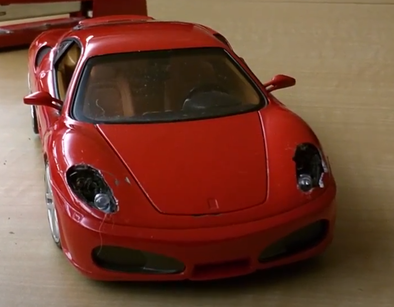
The purpose of the Automatic Night Light Project (referred to in this report as the “ANL” and the “ANL Project”) was to develop integral building skills and key circuit troubleshooting skills with the use of a digital multi-meter (“DMM”). These skills turned the ANL into an exciting product enclosed in a fun chassis. There were two key skills acquired by the ANL Project. The first skill which was acquired related to building and craftsmanship. This skill was required to mount the ANL circuit into a model car chassis. Mounting the circuit into a model Ferrari with the two night lights as headlights proved to be more challenging than originally conceived. This part of the project required an understanding of how the circuit worked, together with numerous modifications to the car chassis to house the circuit. The second skill was troubleshooting. On the first attempt to test the ANL circuit once it was mounted into the car chassis, the circuit failed. The failed ANL circuit required serious troubleshooting of the wiring, circuit board and components in order to make it function.
Reference
Procedure
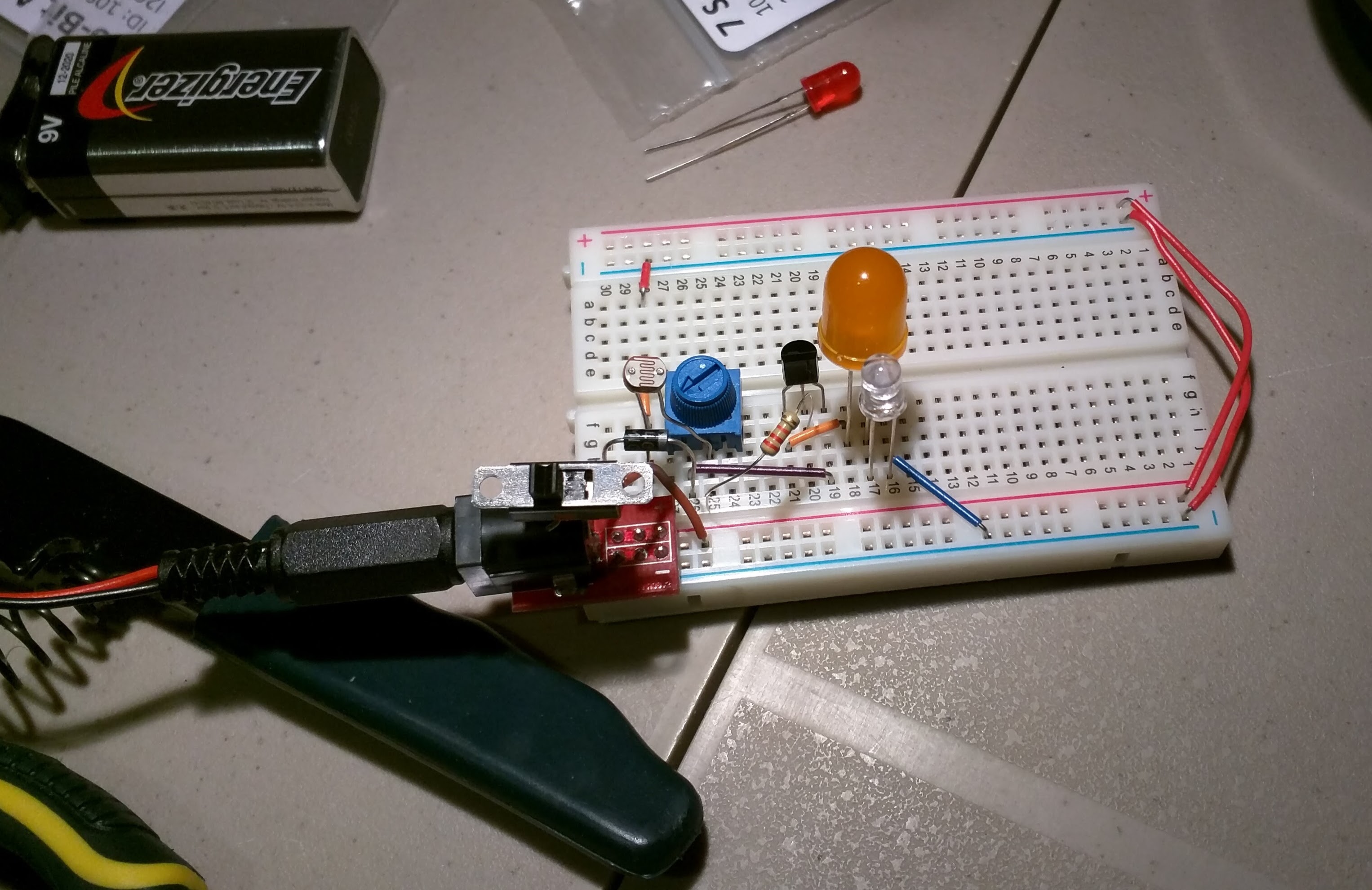
The ANL circuit consists of two LEDs, a transistor, a potentiometer and a Light Dependant Resistor (“LDR”). The circuit works as an ANL due to the presence of the LDR. Specifically, the LDR goes up when there is more light in the room and down when there is less light. This means that the two LEDs only power on when there is low light. The LDR is connected to the base pin of the transistor and the LEDs are connected to the emitter pin of the transistor. When the transistor is set up in this manner, the LEDs are only provided with electricity when the LDR’s resistance is low enough to actuate the base pin of the transistor feeding the LED’s electricity.
| Parts List |
|---|
| 2 Blue LEDs |
| 100k Ω Potentiometer |
| 22k Ω Resitor |
| 470 Ω Resistor |
| Light Dependent Resistor (LDR) |
| NPN 3904 Transistor |
| DC Barrel Jack |
| 9V Power Supply |
| Ferrari Model Car |
The first step to building the ANL circuit was prototyping the circuit on a breadboard. This involved a careful inspection of the circuit diagram and translating the diagram onto the breadboard.
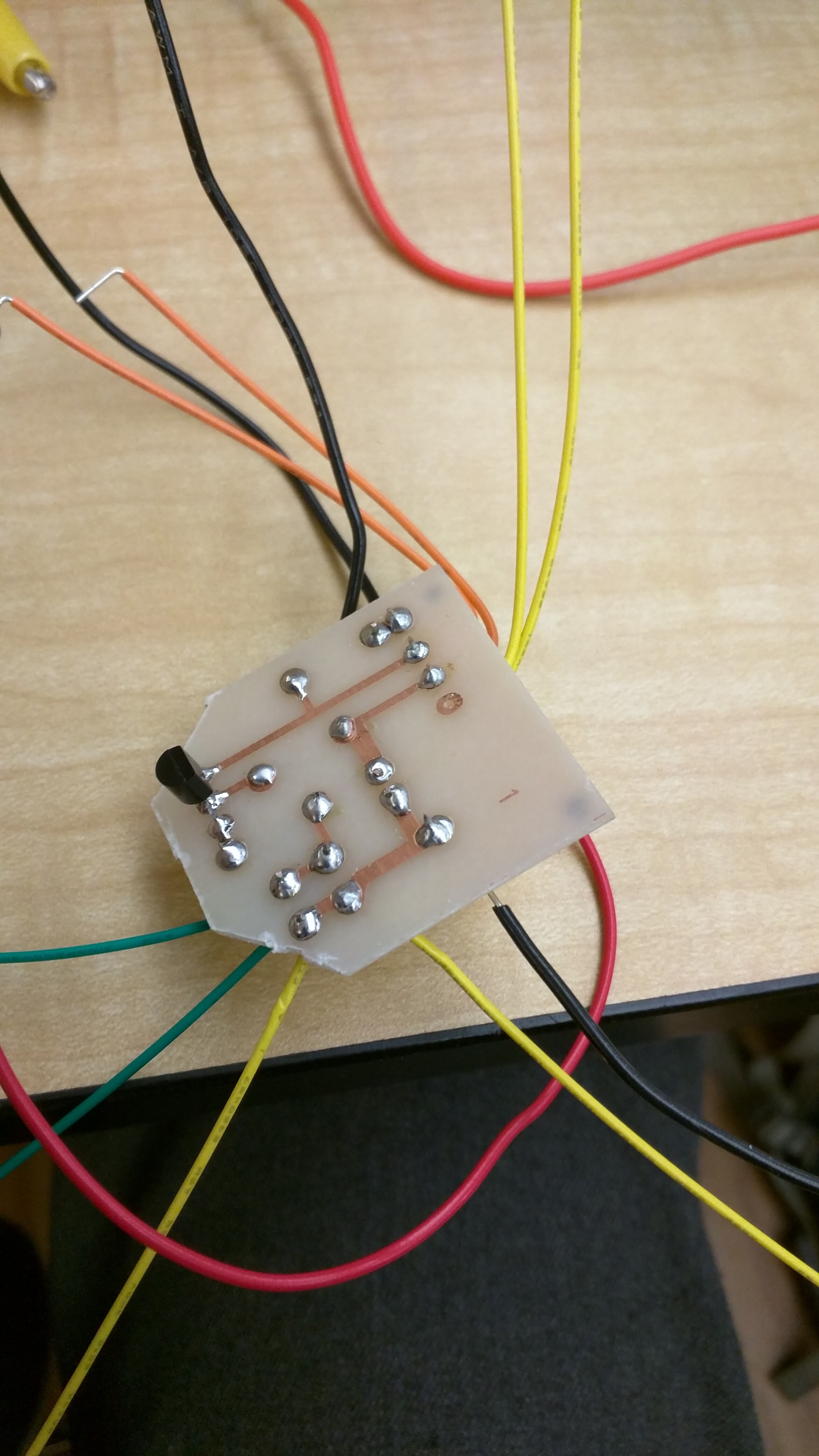
The second step was soldering the wires for the components of the circuit to the board. This step was particularly challenging as it also required reducing the size of the circuit board in order to accommodate it into the hood of the model car chassis, as well as routing the wires through the chassis.
The third step was mounting all the components into the chassis and connecting them to the circuit board. The components were connected to the circuit board with the wires that had already been pre-soldered to the circuit board. Once all the components were connected and a first attempt was made to test the ANL circuit, the circuit failed. At this point, troubleshooting commenced. The circuit was tested with a DMM by using the continuity function. This function checks if electricity is flowing between the two points the DMM is connected to. After an arduous process of testing and checking all connection points of the circuit, it was discovered that a wire connected to the potentiometer got disconnected from the circuit board. After resoldering the wire to the circuit board, the ANL circuit was tested and proved to function correctly. Once a functioning ANL circuit was achieved, the building process was concluded with cable management and the mounting of the LEDs and power jack.
Media

Conclusion
In conclusion, the Automatic Night Light Project was very challenging but rewarding. The ANL project also developed the two key skills of building and troubleshooting with a DMM. The result was a customized awesome looking night light.