
Astable Multivibrator
Purpose
The purpose of the Astable Multivibrator project (the “AM”) was to learn essential circuitry skills for the ACES program, as well as translate those skills into a fun media, by creating a lighting system for a Halloween “jack-o-lantern” pumpkin. There are three key circuitry skills that were acquired by completing the AM project.
The first skill was to move from a prototype circuit on a breadboard to a final product soldered to a Printed Circuit Board (a “PCB”). A PCB is a thin board made of fibreglass, composite epoxy or a different laminate material and contains electrically conductive pathways. Components can be installed and connected to the pathways of a PCB to create a circuit. The PCB is a ubiquitous component of computers and other electronics, hence the necessity of mastering this skill.

The second skill was to learn proper techniques for soldering components to a PCB. Proper soldering techniques are essential to ensuring the proper functioning of the components. The third skill was to interpret the circuit diagram provided for the project and successfully translate it to a prototype circuit on the breadboard, and ultimately to a final product on a PCB.
Reference Circuit

Procedure
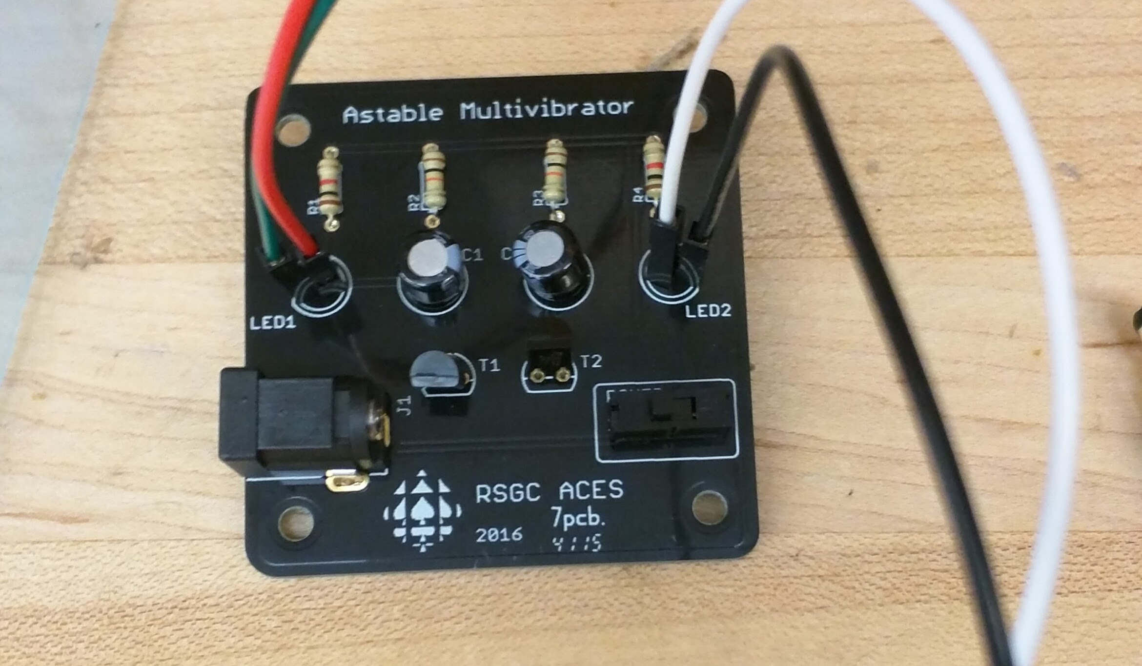
An AM is a circuit with two transistors that work in unison with two capacitors to oscillate Light Emitting Diodes (“LEDs”). The procedure for creating the AM in this project was comprised of 3 steps: prototyping, soldering and pumpkin fitting. The first step to creating the AM was prototyping. This consisted of interpreting the circuit diagram and realizing the circuit on a breadboard. The circuit on the breadboard was realized by analyzing the diagram very carefully and understanding how the components of the circuit are linked together.
Once the prototype circuit functioned correctly, the second step was to create the final version of the AM by successfully soldering the necessary components to a PCB. The soldering was completed by utilizing the helping hands in the DES lab where the PCB was clipped into the helping hands to be soldered. One important soldering technique was to work quickly to prevent overheating the components and causing them to fail. After completing the soldering process, the third step was to fit the PCB and LEDs inside a Halloween carved “jack-o-lantern” type pumpkin. Each eye of the jack-o-lantern was fitted with the two LEDs. In each eye of the jack-olantern, there were toothpicks placed to hold up the LEDs in the eye cavities of the jack-olantern. A video demo of both the prototype, soldered PCB and pumpkin assembly are given in the media section.
Media
Conclusion
In conclusion, the AM project was very rewarding as it allowed the development of three key circuitry skills (applying a prototype to a PCB, soldering, and interpreting circuit diagrams) into an exciting working product.