STM32 FSAE Steering PCB
Introduction
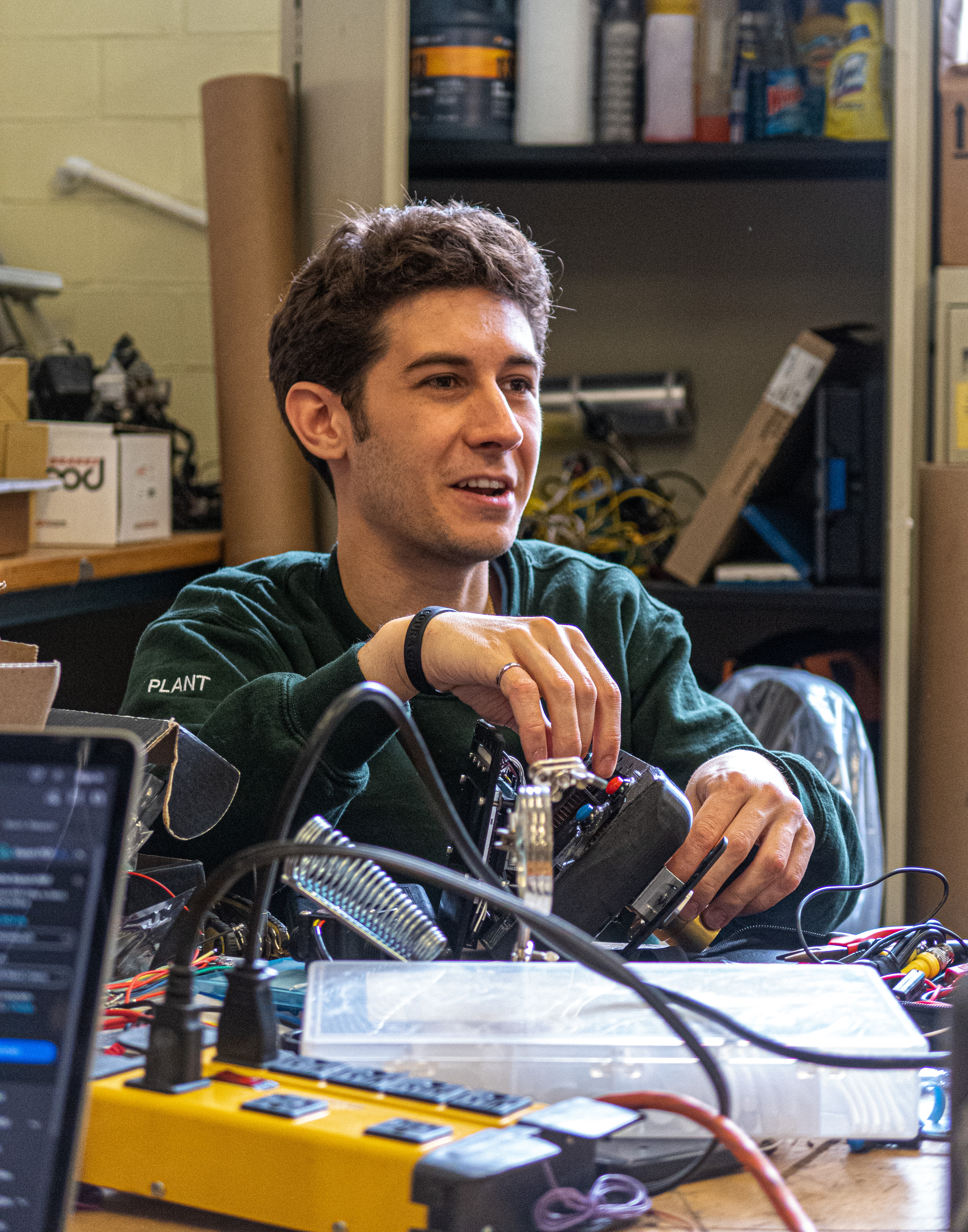
The Steering PCB (hereby referred to as SPCB) was one of my final projects before graduating and ending my time on the Queen’s Racing Formula SAE Team. The SPCB serves as a driver dashboard and gear-shifting interface fully packaged into the steering wheel of the racecar. This design attempts to mirror the steering wheels used in formula one where the display and related electronics are packaged into the steering wheel so that the driver can always see the display without obstruction from steering wheel movements.
The SPCB builds on the work done in the Debugger and Mock ECU projects by employing an STM32 microcontroller. In the past, the team’s dashboard has been Arduino based. The goal of SPCB is to upgrade the microcontroller to STM32 and provide a truly re-usable design that allows the team to continue to build out more sophisticated firmware in the coming seasons.
STM32 provides two advantages; speed and native CAN buses. Unlike the Arduinos based on ATMEGA328P that have been used in the past, the STM32F4 used in the SPCB has two native CAN controllers. The native CAN controllers open a variety of possibilities for multiple CAN buses in the vehicle, gatewaying, interrupt driven message transmitting and more. Moreover, the STM32 is signifcantly faster and is able to drive the steering wheel’s display. STM32 and other ARM based microcontrollers are also very commonly used in industry. As a result, there is a wealth of resources for bringing up new tools and improving the team’s firmware development workflow to an industry representative standard. In this first implementation, the team leveraged the pre-existing arduino toolchain to quickly prepare firmware for the car’s first drive. However, in future, the team can create their own hardware abstraction layer for the microcontroller and integrate an RTOS without the limitations of the Arduino ecosystem.
The SPCB breaks out IO for the following driver interfaces.
- A high-brightness LCD display for the driver to consume real-time information about the vehicle via ECU CAN data.
- High-brightness RGB neopixels as an easily readable RPM meter telling the driver when to shift (modeled after today’s F1 cars).
- 4 buttons to control which information is on the screen and configure the display.
- 2 button inputs for paddle shifting. (The steering PCB is responsible for relaying shifting commands to the vehicle’s ECU).
The following subsections explain how the functionality listed above was implemented at both the hardware and firmware level.
Hardware Design
The schematic design of the SPCB is broken down into several sub-circuits in a multi-sheet design on Altium. The following sections break down each component of the SPCB schematic design.
Power Distribution
The SPCB manages the following three power domains.
- 12V bus voltage from the car’s battery.
- 5V power for the neopixel LEDs and LCD display.
- 3.3V logic power for the microcontroller and LCD SPI interface.
There are two LDO voltage regulators that provide the 5 and 3.3V rails
respectively. The 5V regulator uses the 12V bus voltage as input voltage. The 5V
output is used to feed the 3.3V regulator. There is no dedicated control of
either power rail and both will power up as soon as a 12V bus voltage is
applied. A dedicated LED is provided on each power rail as a visual indication
of board power. The power schematic is located in the Power.SchDoc file
here.
Neopixel Control
Neopixels are used as the RPM indicator lights on the SPCB. Neopixels take their RGB color and brightness commands via a one-wire data interface. This interface is bi-directional and uses 5V logic to match the 5V supply voltage.
The 5V logic of the neopixels does not match the 3.3V logic of the STM32 microcontroller commanding the neopixels. This mismatch can damage the STM32 with overvoltage and prevent the neopixels from functioning correctly. The solution is to use a logic level translator. The translator steps the STM32 control signal up from 3.3 to 5V. Conversely, it steps any signals driven by the neopixels down from 5 to 3.3V allowing both devices to communicate seamlessly.
The level translator and neopixel schematic is located in Neopixel.SchDoc
here.
LCD Control
The microcontroller communicates with the LCD via SPI. Rather than sending a
full framebuffer, individual SPI commands are sent to an FT813 display
controller. As a result, the PCB only needs to provide a SPI interface to the
LCD. The schematics are located in MCU.SchDoc and Connectors.SchDoc.
Debug Interface
The SPCB implements both JTAG and USART debug interfaces to be used in conjunction with the custom Queen’s Formula Debugger. In future revisions, this debug interface can be integrated directly into the PCB. However, this was not done on the first revision due to the chip shortage and difficulty acquiring STM32 chips specifically. For more details on the microcontroller implementation and schematics, please refer to the MCU section of the ME Project which uses the same controller.
CAN Bus Design
The SPCB only breaks out a single CAN bus that is used to consume information from the car’s ECU. One CAN peripheral on the microcontroller is unused. A physical switch is used to determine whether the bus is terminated at the transceiver. The objective of this feature is to provide harnessing and termination flexibility. Sadly, a copy-paste error was made that connected the termination resistor to the wrong net, which stopped this feature from working. The error should be corrected in future revisions of the design.
Project Viewer
Embedded below is the Altium project view of the SPCB project. The embedded viewer contains all the schematics that constitute the multi-sheet design as well as the PCB layout, BOM and 3D renders. The complete Altium CAD files can be found here.
Firmware
Board Bring-up
Basic bring-up of the SPCB was done using the Queen’s Formula Debugger and the STM32 Arduino Board support package. While the team is moving away from the Arduino ecosystem, it still provides useful tools for fast iteration and testing of the board’s functionality. The Arduino-based Adafruit Neopixel library was used to quickly verify the level translator circuit and Neopixel functionality.
The FT813 display also worked “out-of-the-box” thanks to Rudolph Riedel’s https://github.com/RudolphRiedel/FT800-FT813. The team later created a fork of this library to ensure it would compile in our broader C++ project.
The final step of board bring-up was to ensure that the SPCB could send and receive CAN bus messages. This was quickly validated by bringing in our existing STM32 CAN bus driver and interfacing with the car’s MoTec ECU.
Mitigating a Hardware Issue in Firmware
While testing the full range of brightness on the display, we quickly found that the display started to flicker and fail. This was initially thought to be a display, but an oscilloscope probe to the 5V power rail showed that we were exceeding the 1A current capacity of the 5V LDO and bring down the rail. This issue was mitigated in FW by reducing the brightness of the display and the neopixels. Luckily, the display and neopixels still remained readable under sunny conditions in vehicle testing.
CAN Bus Data
The SPCB firmware has access to a wealth of sensor data from the vehicle’s ECU and PDM. In the past, the team has not fully leveraged this data. With the SPCB, the team is able to provide the driver with all the vehicle’s CAN data in real time. This includes but is not limited to:
- Speed
- Gear
- Battery / Bus Voltage
- RPM
- Engine Temperature
- Coolant Temperature
- Clutch State
- Power Feed Health
- Throttle Position
- Brake Position
- CAN Bus Health
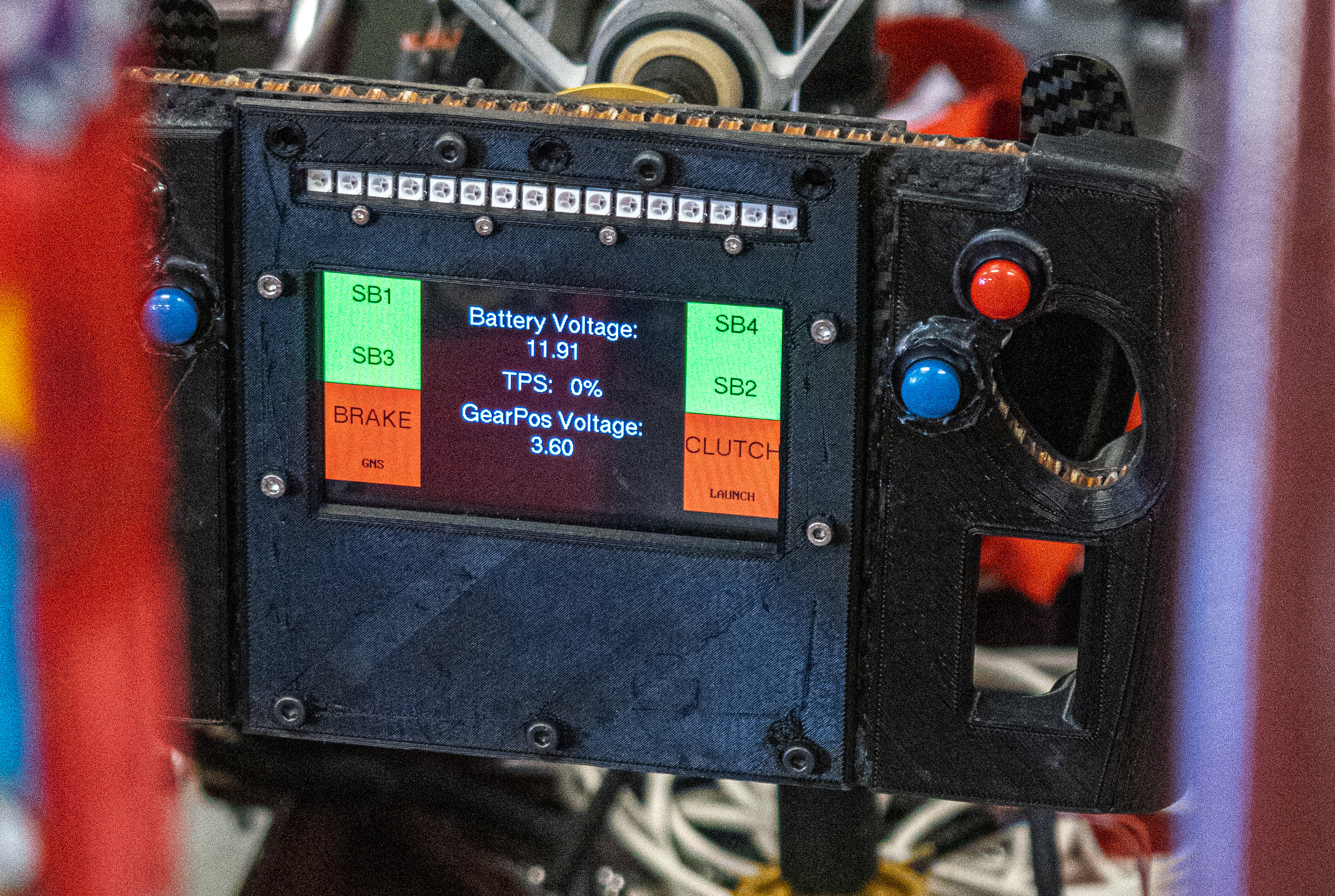
Typically, the driver is only concerned with the gear, RPM, and vehicle speed. This data was included on a dedicated drive mode screen with the remaining data accessible on a debug screen through a button. One of the debug screens is shown in the thumbnail for this post. The display allowed the team to quickly spot-check vehicle health without connecting a laptop to the car.
Decoding the ECU data in real time was handled by Jacob Chisholm’s CAN Bus Abstraction Layer (CAL) library. Jacob created this general library to decode the messages from our MoTec ECU and PDM. In the steering firmware, the CAN message’s ID and payload would be passed into a library function call to collect the relevant data making it easily accessible for other team members working on the driver interface.
Harnessing and Vehicle Interface
Since the SPCB is embedded in the steering wheel of the vehicle rather than in the dashboard, it needs to be able to interface with the vehicle through a quick-release connector.
The team used a quick-release connector with an 8-pin interface. 12V power is fed to the quick-release and regulated locally on the SPCB to help with current capacity constraints. CAN bus is also routed through the quick-release. The 4 remaining signal lines were used as hard lines for the shifter paddles and other buttons to the ECU. The SPCB has the ability to transmit switch statuses over CAN, but the extra 4 signals served as a backup.
Similarly to the SPCB itself, the vehicle harness design was also captured in Altium. Special thanks to Joe Wigle for his support in the construction of the vehicle harness and the schematic design. The schematic for the harness is given below:
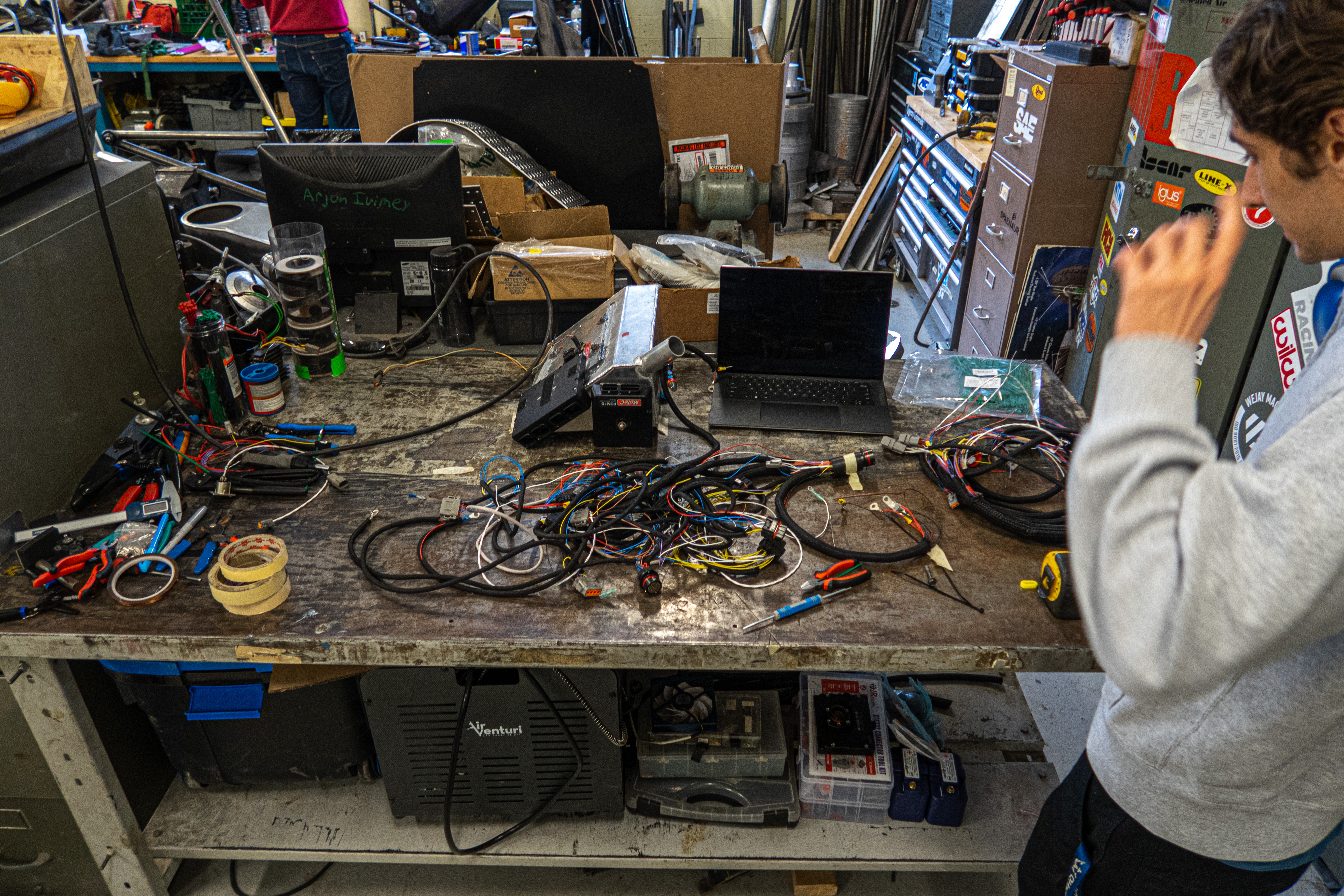
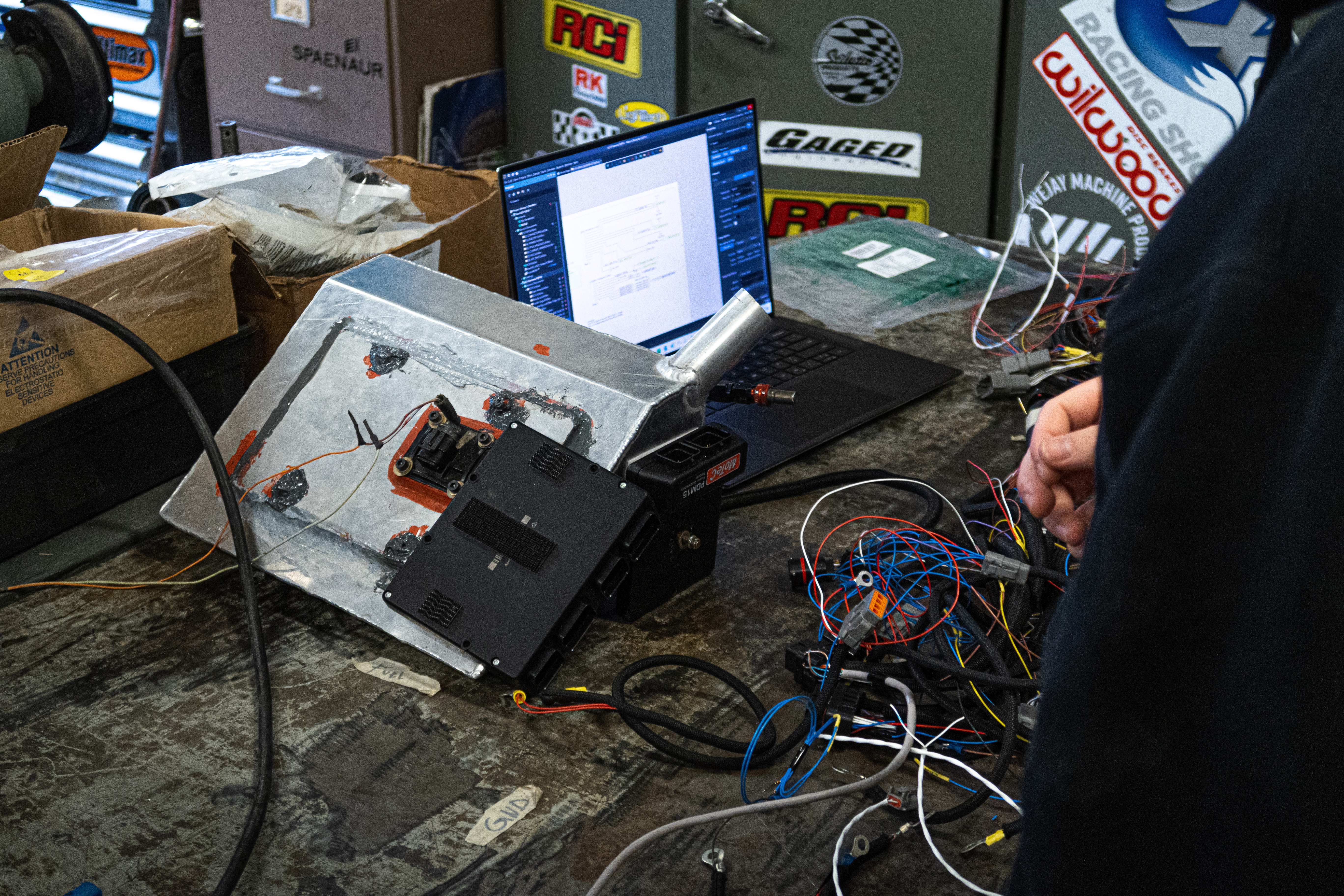
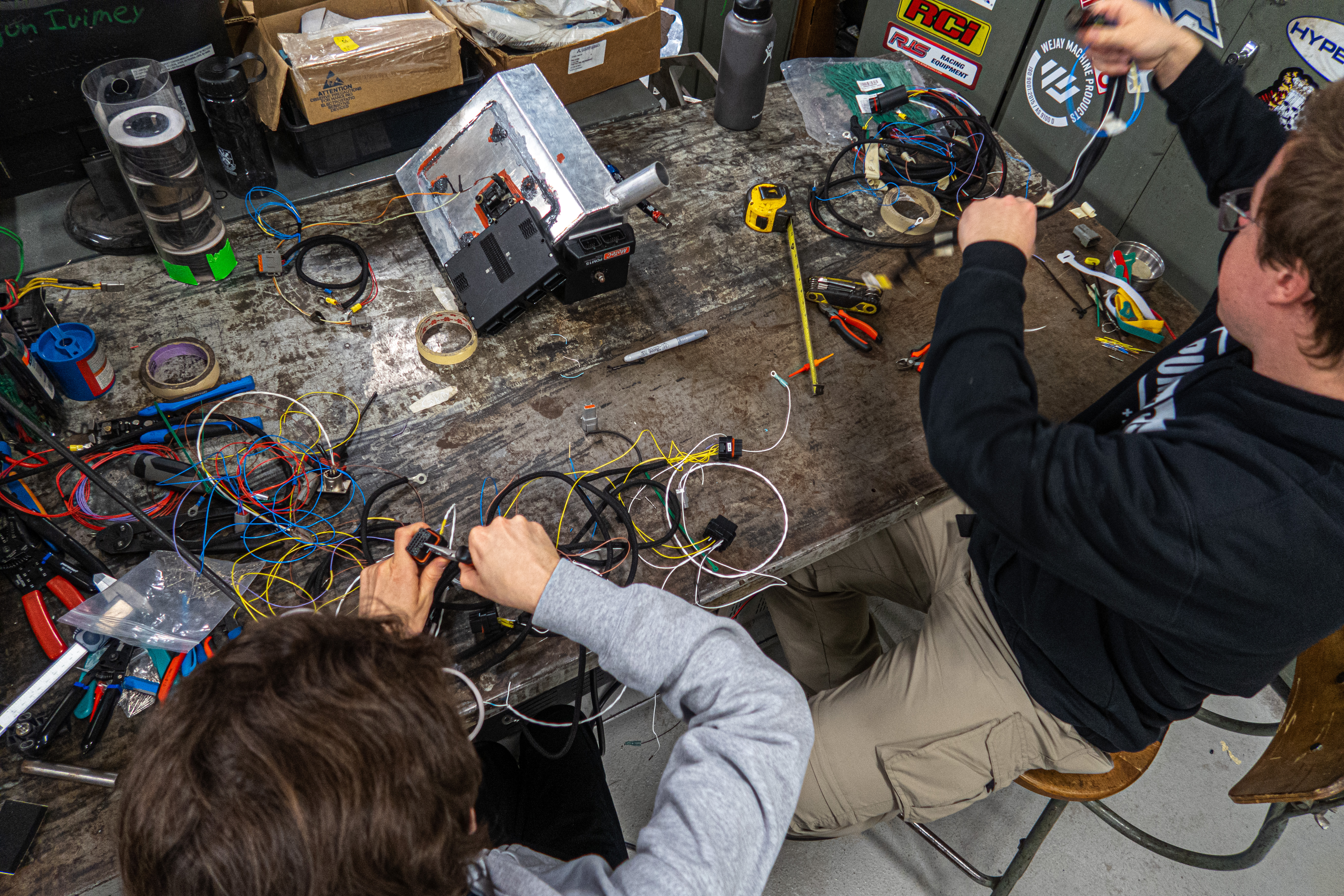
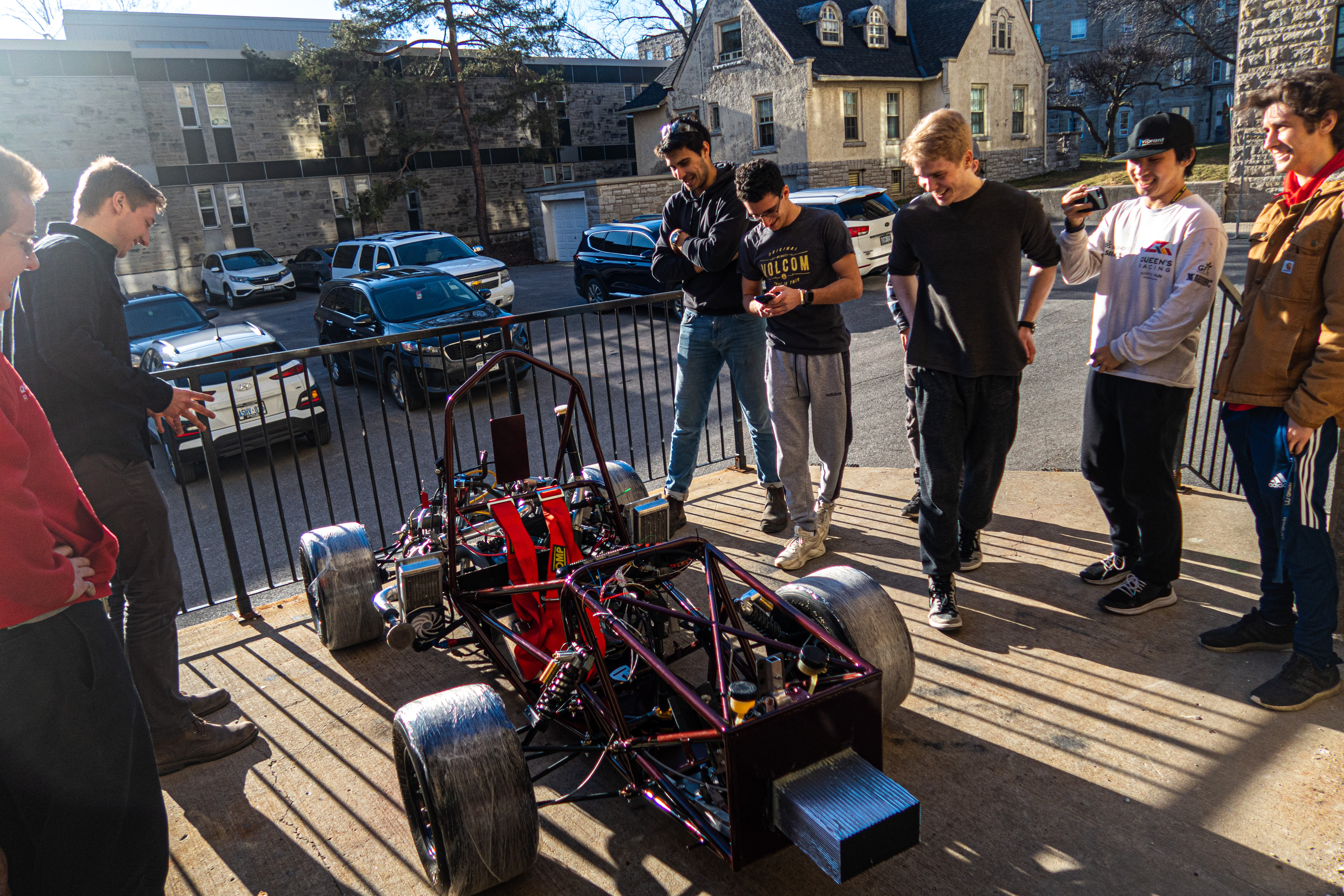
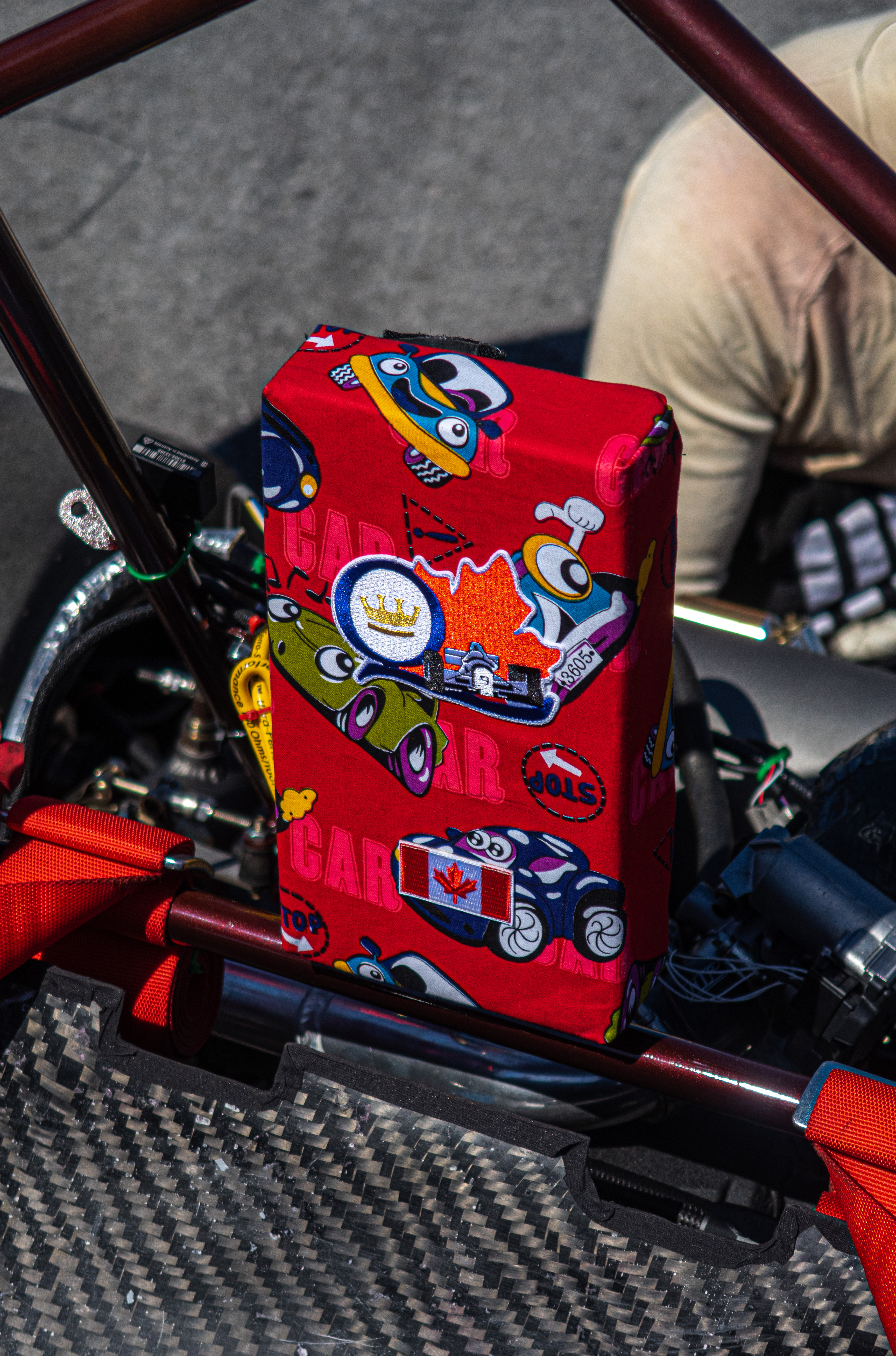
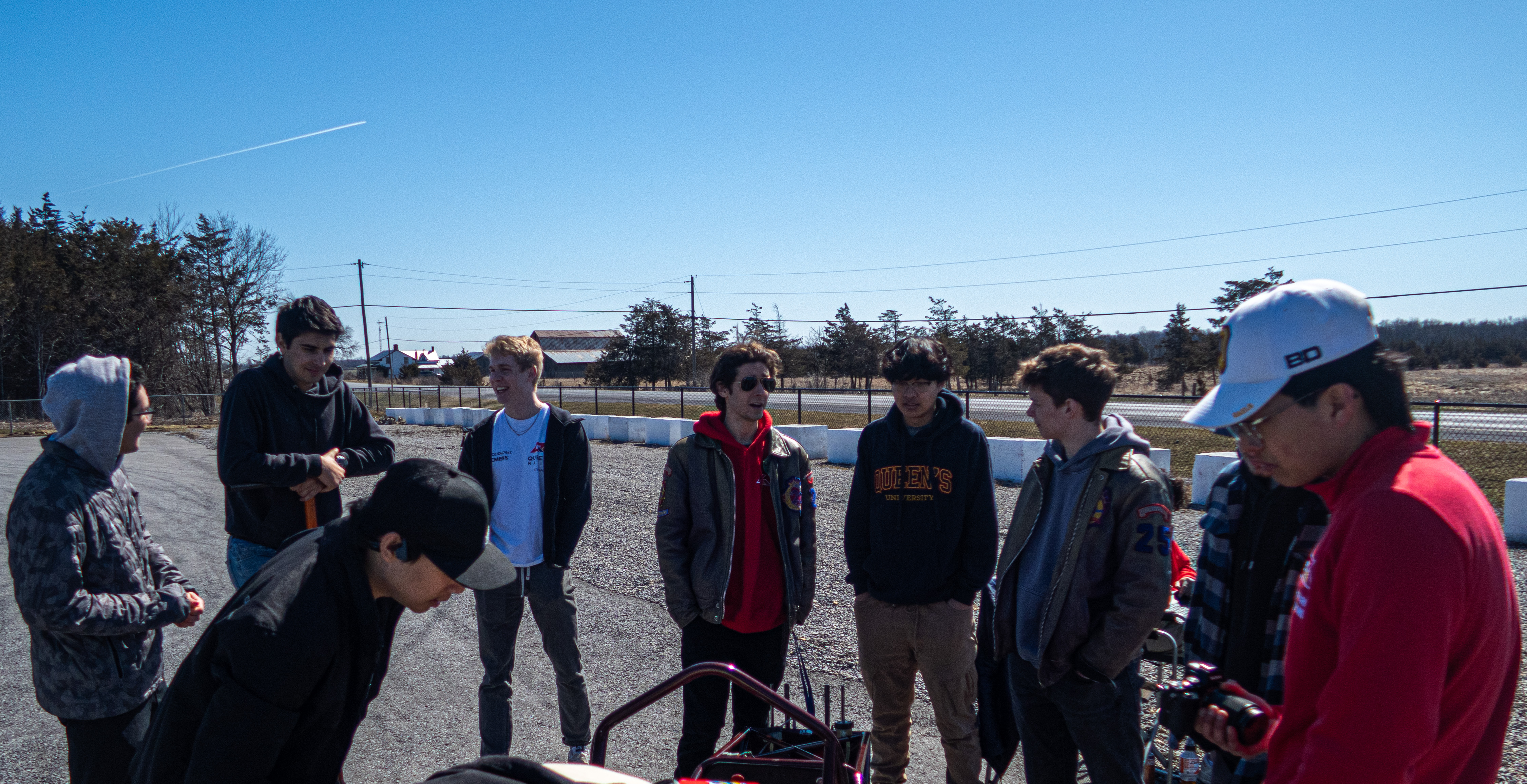
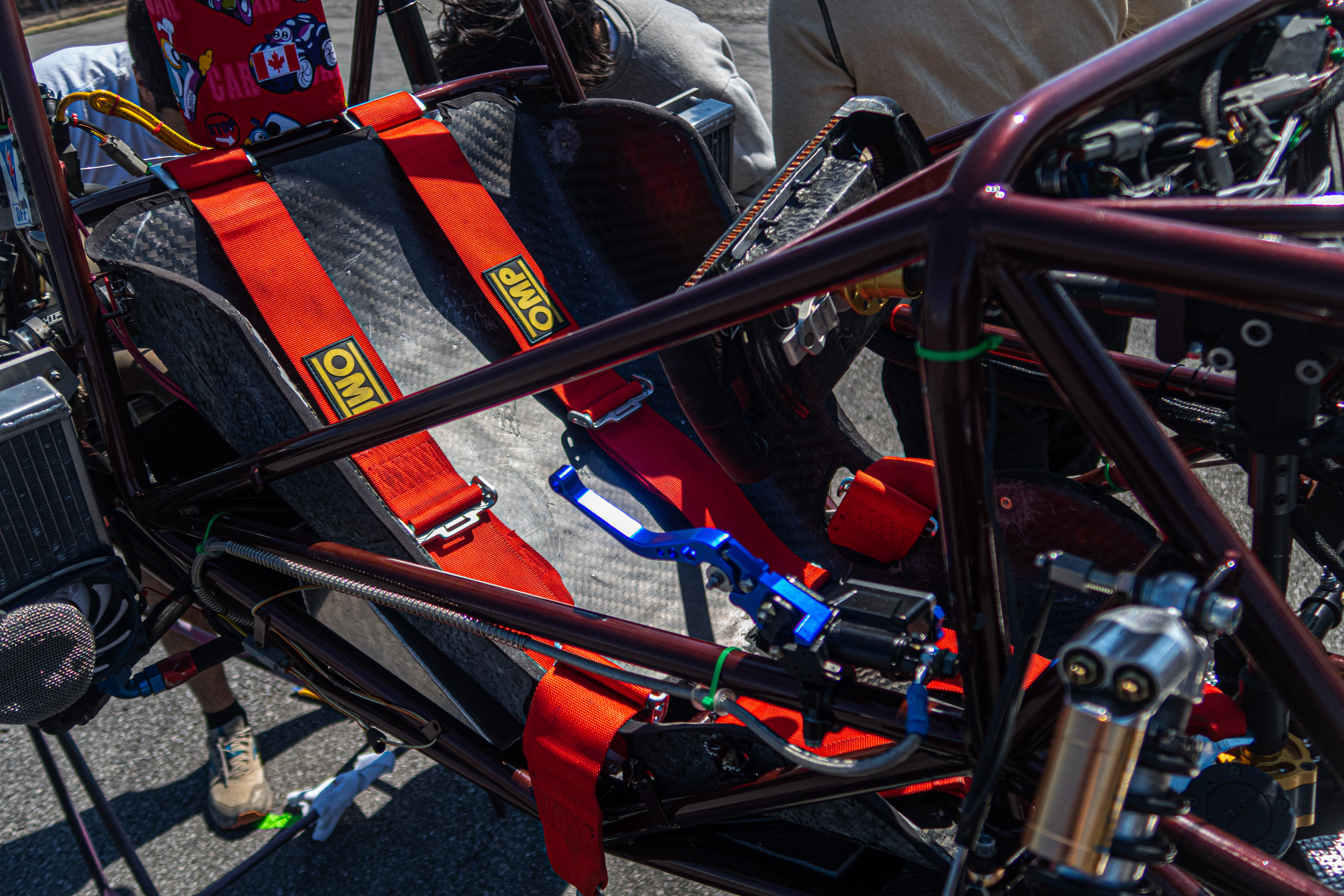
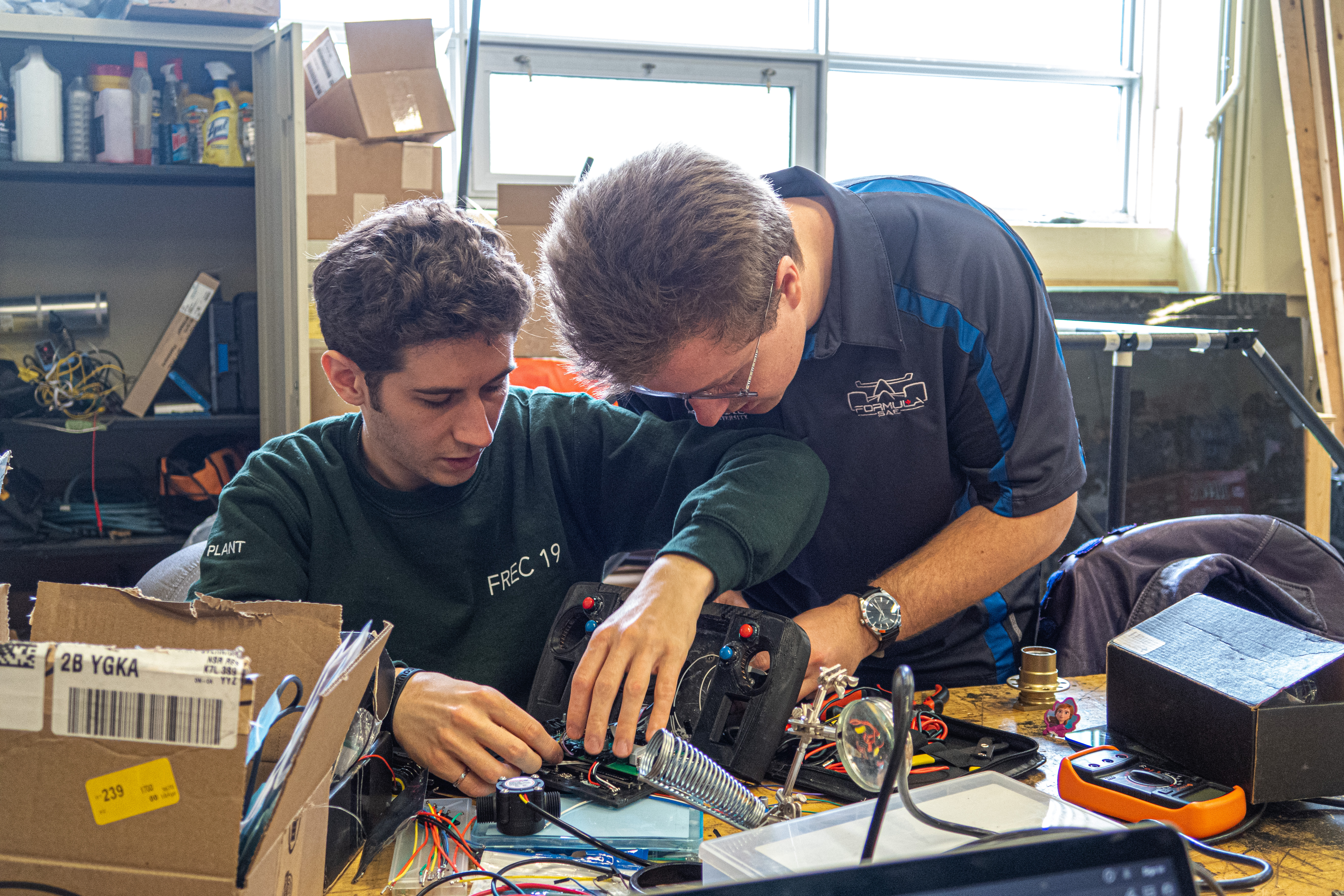
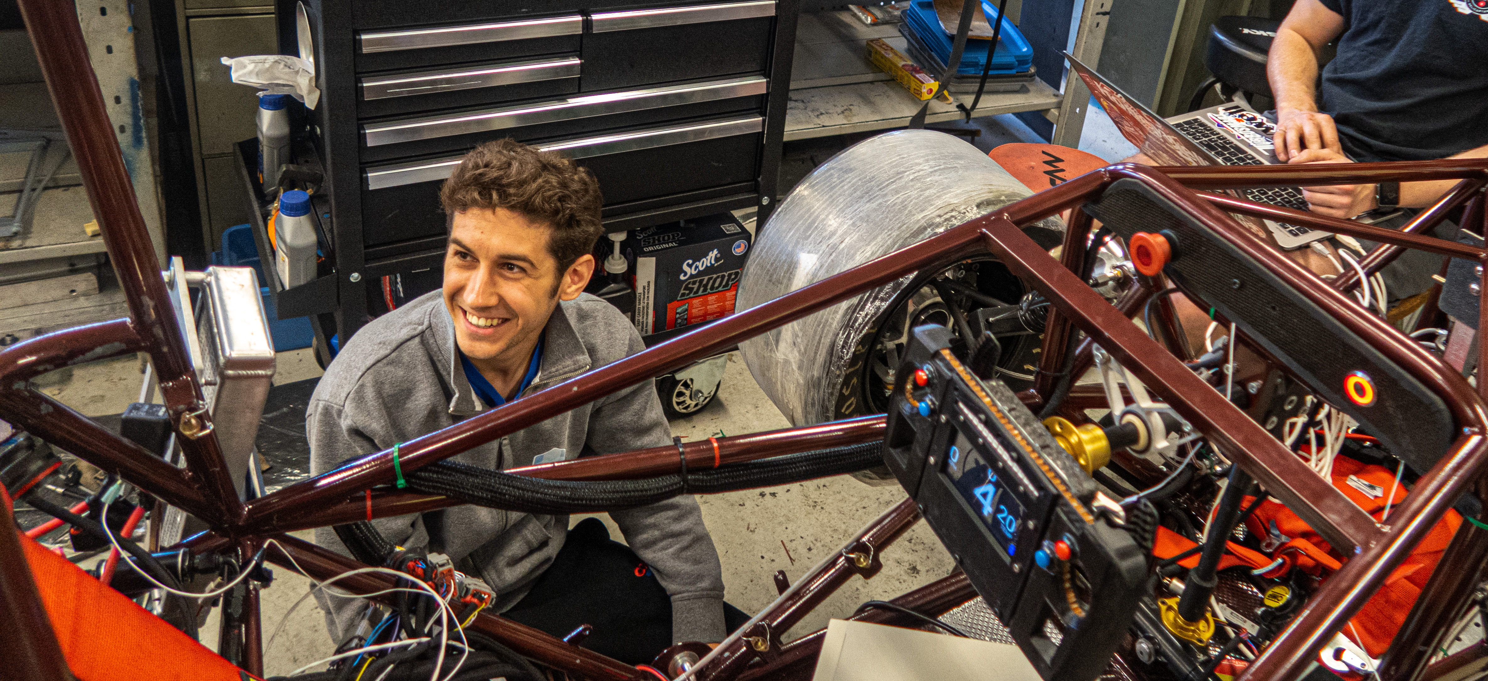
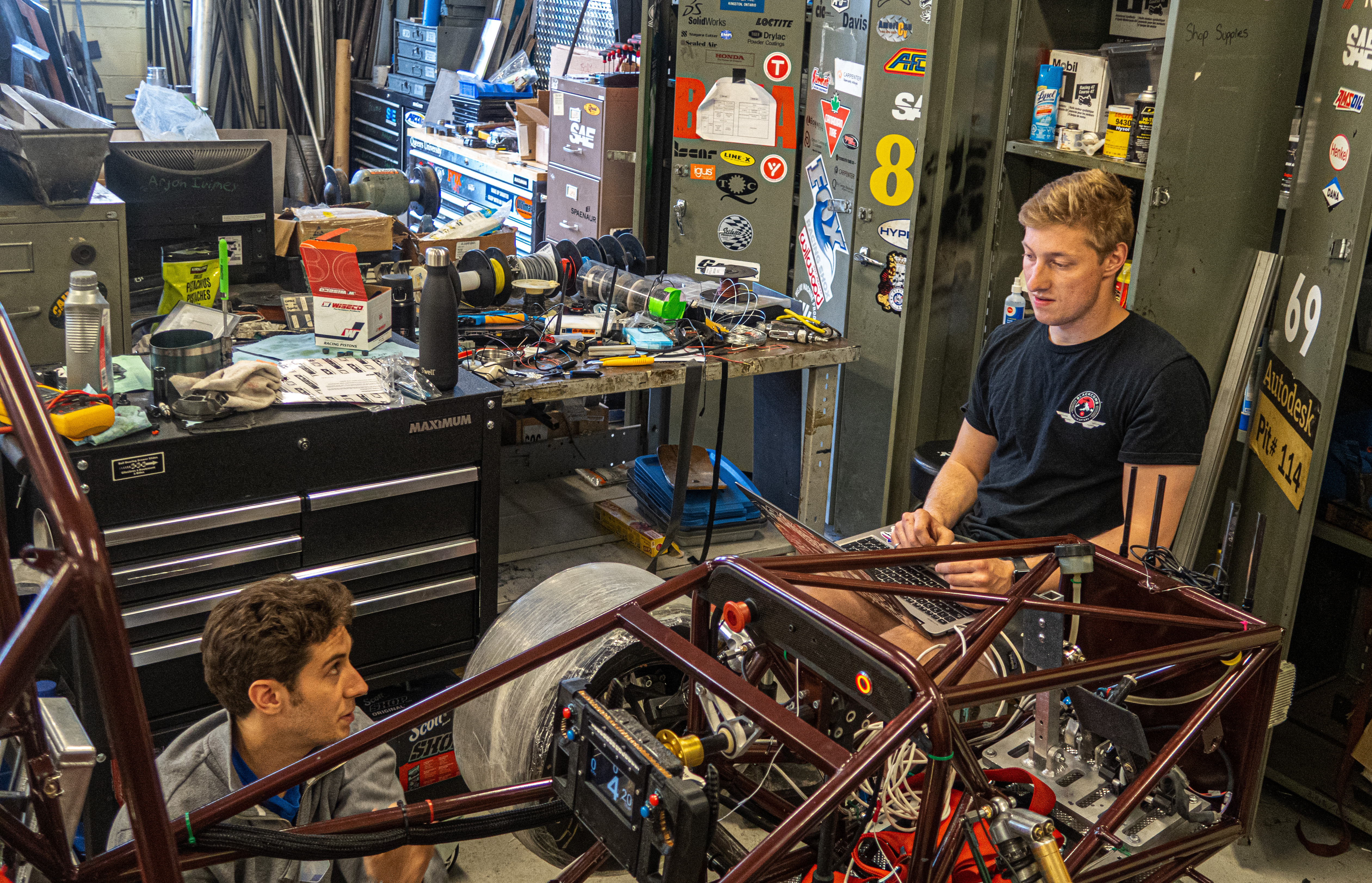
Photo and Video Gallery
Below is a collection of photos and videos from the 2023 formula season which include the SPCB.
Conclusion
Overall, the SPCB was a large user-facing project that I was glad to undertake before ending my time on the formula team. The SPCB completes the team’s transition to STM32. I look forward to seeing what the team does with this reference design and the underlying firmware!