555 Timer Based LED Matrix Animations
Purpose
The purpose of the 555 timer-based LED matrix animations project (referred to in this report as the “TBMA project”) was to demonstrate how a 555 timer could still be used in the context of microcontrollers, as well as improve programming skills and understanding of the 595 shift register.
3 key engineering skills were improved upon in the TBMA project:
Programming skills were improved as a result of having to program a smaller microcontroller with less SRAM and program space to work with, as well as having to program two daisy chained shift registers to display the desired images on the LED matrix. Soldering skills were highly improved upon during this project due to the fact that all of the columns on the half + size breadboard PCB were utilized in the circuit, thereby requiring an extensive amount of soldering and leaving little room for error in the soldering process. Circuit skills were also refined during this project as the project required extensive wiring and troubleshooting of the circuit and less attention to the code.
Reference
http://lucidtronix.com/tutorials/40 http://www.protostack.com/blog/2010/05/introduction-to-74hc595-shift-register-controlling-16-leds/
Procedure
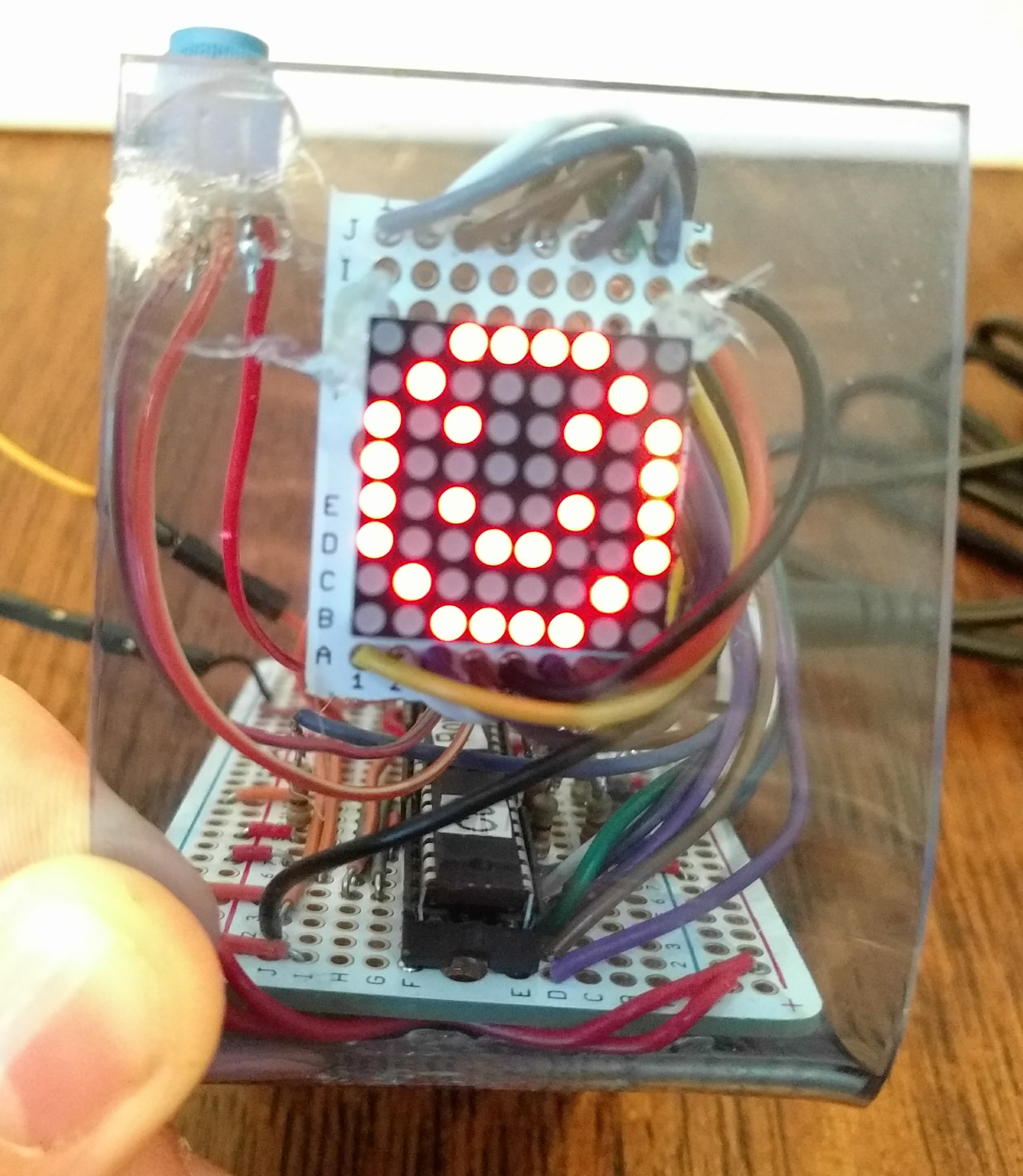
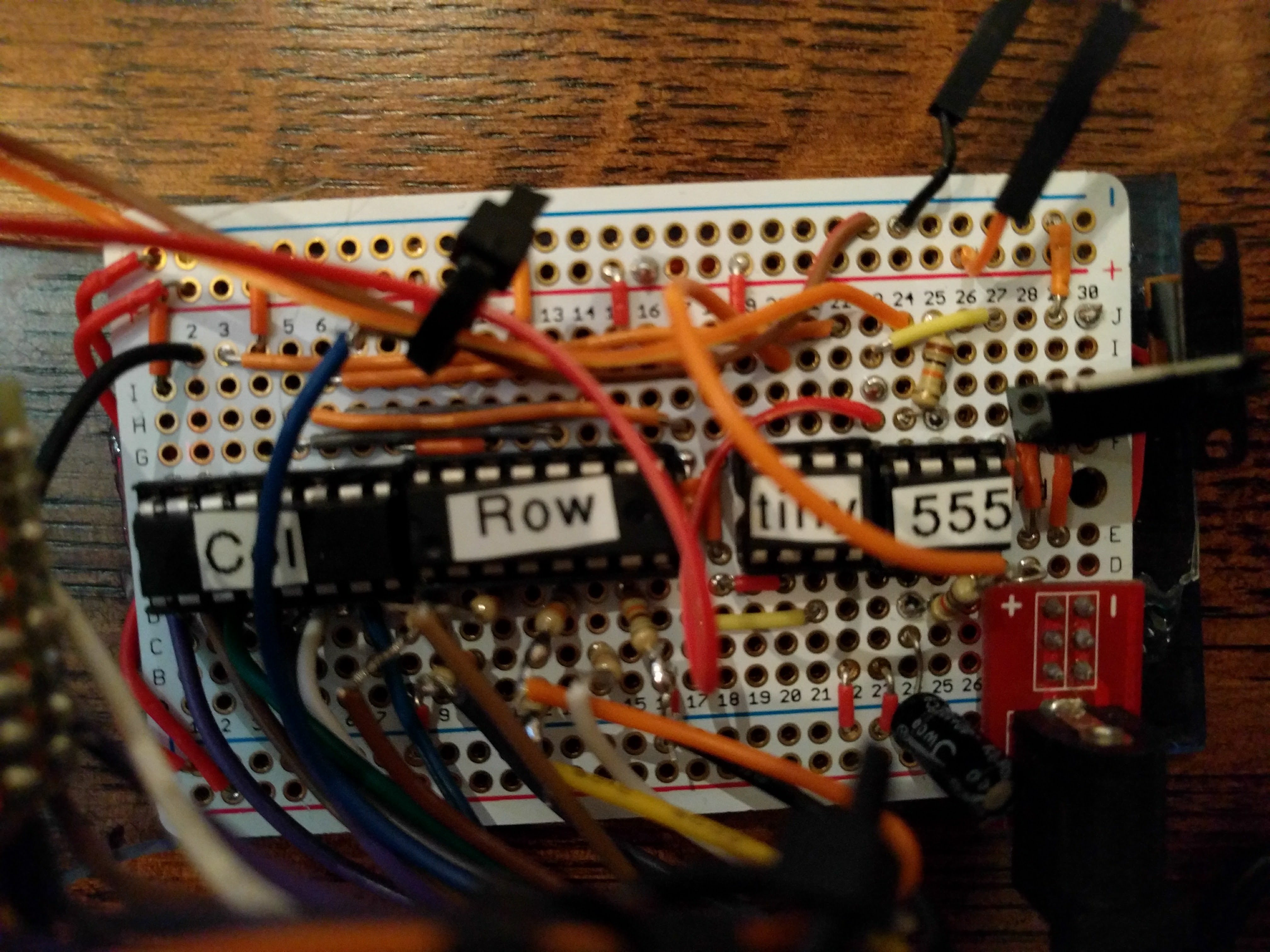
The TBMA project circuit was made up of 2 595 shift registers, an ATtiny85
microcontroller, a 555 timer and a 8x8 LED matrix. The 555 timer establishes an
astable square wave pulse that is adjustable by a 10k potentiometer. The output
pin of the 555 timer, which emits the pulse, is hooked up to the external
interrupt pin of the ATtiny85. Each time the output pin of the 555 goes high, an
interrupt is triggered that communicates to the ATtiny85 to show the next frame
of the animation. This effectively allows the 555 timer and the user-adjustable
potentiometer to control the framerate of the animations shown on the LED
matrix. An additional three digital I/O pins of the ATtiny85 are hooked to the
data, latch and clock pins of the shift register handling the columns of the LED
matrix. The shift register controlling the rows is daisy- chained to the shift
register controlling the columns of the LED matrix. The daisy-chaining of the
two shift registers gives the ATtiny85 access to 16 new output pins, which
control the 64 total LEDs on the LED matrix through a process in the code called
scanning. The scanning takes place within a function in the code called
displayBitMap(). A bitmap consists of an array that holds 8 bytes. The
displayBitMap() function shifts the binary values from the first byte of the
array into the column shift register and as it is the first byte of the array,
it is shown on the first row of the LED Matrix. The function then turns off the
first row and shifts out the byte to the column shift register to be shown on
the second row. This process continues until each row has been shown once.
Despite one row being enabled at a time, the scanning process takes place so
rapidly that it appears as though all of the individual illuminated rows on the
LED matrix are illuminated simultaneously. This is due to an optical illusion
called persistence of vision. Persistence of vision is an optical illusion
whereby multiple discrete images blend into one. In this case, the individual
illuminated rows on the LED matrix are perceived as one image.
| Parts List |
|---|
| 2 595 Shift Registers |
| ATtiny85 Microcontroller |
| 555 Timer IC |
| 8x8 LED Matrix |
| 8 x 330Ω Resistors |
| 1k Ω Resistor |
| Adafruit Half Breadboard PCB |
| Blue Acrylic Chassis |
| 9V Power Supply |
The first step in the construction of the TBMA project was the creation of the circuit. The circuit was initiated by establishing an astable pulse from a 555 timer. The 555 timer was then hooked to a potentiometer so the speed of the pulse could be adjusted. Additionally, an ATtiny85 was added to the circuit along with two 595 shift registers. The ATtiny85 was hooked up to the output pin of the 555 timer, along with the first of two 595 shift registers. The second shift register was daisy-chained to the first, allowing the ATtiny85 to control 16 new pins with only 3 of its own. Following the wiring of the integrated circuits (ICs), the next step was to set up the LED matrix. Setting up the LED matrix was an arduous process of testing each pin on the matrix to determine what column or row it represented. The purpose of each pin on the matrix was noted on a diagram that was used for reference when wiring the matrix through different iterations of the circuit. The final step in the construction of the circuit was the connection of the LED matrix to the shift registers and the mapping diagram was used for reference during this step.
The second step in the construction of the TBMA project was creating the code to
drive it. The code needed to facilitate communication between the ATtiny85 and
the shift registers, as well as read the pulse from the 555 timer. The approach
to communication with the shift registers was to use a custom function called
writeRegs(). The writeRegs() function took the data to shift out from an
array of Booleans that contained the requested state of all the shift register
pins available. In other words, the state of a pin on the shift register can be
changed in the Boolean array and the change can be written later by calling
writeRegs(). This arrangement allowed a large amount of flexibility that was
initially thought to be impossible with the use of daisy-chained shift
registers.
The final and most difficult step of constructing the TBMA project was soldering. Since the circuit contained 4 ICs and an LED Matrix, a substantial amount of wiring had to fit onto a half+ size Adafruit breadboard PCB. Specifically, upon completion of the soldering process for the circuit, all of the available columns on the board had been completely utilized. The limited space made for a challenging soldering process where any errors would require restarting the entire process. However, it should be noted that the breadboard prototype was available for reference when soldering, which helped with the process immensely.
Media
Code
/*
Author: Ethan Peterson
Date: November 26, 2016
TEI3M
*/
// Define Shift Register Pins:
#define clk 3
#define latch 4
#define data 0
#define shiftRegNum 2
#define shiftRegPinNum shiftRegNum * 8

// create a boolean array to store the state of every
// 595 pin available
bool registers[shiftRegPinNum];
// frame variable that is incremented every time the output pin of the 555 goes
// high
uint8_t frame = 0;
uint8_t animations[][8] = { // 2d array storing bitmaps for every individual
                            // frame of the animations
    {                       // happy - sad animation
     B00111100, B01000010, B10100101, B10000001, B10100101, B10011001,
     B01000010, B00111100},
    {B00111100, B01000010, B10100101, B10000001, B10111101, B10000001,
     B01000010, B00111100},
    {B00111100, B01000010, B10100101, B10000001, B10011001, B10100101,
     B01000010, B00111100},
    {B00111100, B01000010, B10100101, B10000001, B10100101, B10011001,
     B01000010, B00111100},
    {B00111100, B01000010, B10100101, B10000001, B10111101, B10000001,
     B01000010, B00111100},
    {B00111100, B01000010, B10100101, B10000001, B10011001, B10100101,
     B01000010, B00111100},
    {B00111100, B01000010, B10100101, B10000001, B10111101, B10000001,
     B01000010, B00111100},
    {// space invader animation
     B00011000, B00111100, B01111110, B11011011, B11111111, B00100100,
     B00011000, B00000000},
    {B00011000, B00111100, B01111110, B11011011, B11111111, B00100100,
     B01011010, B10100101},
    {B00011000, B00111100, B01111110, B11011011, B11111111, B00100100,
     B00011000, B00000000},
    {B00011000, B00111100, B01111110, B11011011, B11111111, B00100100,
     B01011010, B10100101},
    {B00011000, B00111100, B01111110, B11011011, B11111111, B00100100,
     B00011000, B00000000},
    {// pac man animation
     B00111100, B01111110, B11011111, B11111111, B11110000, B11111111,
     B01111110, B00111100},
    {B00111100, B01010110, B10010011, B11011011, B11111111, B11111111,
     B11011101, B10001001},
    {B00111100, B01111110, B11011111, B11111111, B11110000, B11111111,
     B01111110, B00111100},
    {B00111100, B01010110, B10010011, B11011011, B11111111, B11111111,
     B11011101, B10001001}

};

void setup() {
  pinMode(latch, OUTPUT); // data
  pinMode(data, OUTPUT);  // latch
  pinMode(clk, OUTPUT);   // clock
  // reset all register pins
  clearRegs();
  writeRegs();
  // creates an inturrupt where everytime the
  // output pin of the 555 goes high call the nextFrame() function
  attachInterrupt(0, nextFrame, RISING);
}

void clearRegs() { // clears the registers array but does not write the changes
  for (int i = shiftRegPinNum - 1; i >= 0; i--) {
    registers[i] = LOW;
  }
}
void writeRegs() {
  // writes data in the registers array to the output pins of
  // the shift registers
  digitalWrite(latch, LOW);
  for (int i = shiftRegPinNum - 1; i >= 0; i--) {
    digitalWrite(clk, LOW);
    uint8_t val = registers[i];
    digitalWrite(data, val);
    digitalWrite(clk, HIGH);
  }
  digitalWrite(latch, HIGH);
}

void setRegPin(uint8_t i, uint8_t val) {
  // function changes the value of an individual pin on the 595 by changing the
  // value in the registers array where the change can be displayed later
  registers[i] = val;
}
void displayBitMap(uint8_t charMap[8]) {
  // displays a full bit map on the 8x8 matrix
  // by shifting the right byte onto the correct row with one row lit up at a
  // time this is taking place so fast that it looks as though all rows are
  // being illuminated at the same time
  for (uint8_t row = 0; row < 8; row++) {
    // ensure column data is shown on the correct row by illuminating the
    // current one and making the previous one low
    setRegPin(8 + (row - 1), 0);
    setRegPin(8 + row, 1);
    for (uint8_t col = 0; col < 8; col++) {
      if (charMap[row] & (1 << col)) {
        // invert the bit because col pins must be low to be shown
        // due to the way the matrix is configured
        setRegPin(col, 0);
      } else {
        setRegPin(col, 1);
      }
    }
    if (row == 0) {
      setRegPin(15, false); // prevent same byte from being shown on two columns
    }
    writeRegs();
  }
}

void loop() {
  // display animations at the corresponding frame
  displayBitMap(animations[frame]);
}

void nextFrame() { // runs every time the output pin of the 555 timer goes high
  if (frame == (sizeof(animations) / 8) - 1) {
    frame = 0;
  } else {
    frame++;
  }
}
Conclusion
Overall, the TBMA project was an ambitious undertaking in the areas of circuit building, programming and soldering. The project was arduous but highly rewarding upon its completion. The TBMA project allowed the development of essential skills relating to the wiring and programming of shift registers to control LED matrices, making the project a great introduction to potentially more complex projects involving LED matrices.